Trifocal Intraocular Lenses: History, Design, and Clinical Outcomes
The development of trifocal intraocular lenses (IOLs) has revolutionized cataract surgery by enabling patients to achieve clear vision at near, intermediate, and far distances without the need for additional corrective lenses. For more than 15 years, trifocal implants have been the most commonly used intraocular lenses when one of the key goals of cataract surgery is to minimize dependence on corrective glasses. This allows the patient to enjoy clear vision without glasses for distance, near (reading), and intermediate distances (working on a computer). This segment of so-called « presbyopia-correcting » lenses accounts for approximately 11% of the total intraocular lens market for cataract surgery. Trifocal implants make up half of this market in Europe (see clinical trends, ESCRS). This page is dedicated to the technical aspects of pioneering trifocal diffractive IOLs.
???? Key Points
- First trifocal IOL: FineVision (PhysIOL, Belgium), released in 2010
- Design principle: Combination of two bifocal diffractive profiles (+3.50D and +1.75D)
- Light distribution: ~42% far, ~36% near, ~22% intermediate
- Energy efficiency: Only ~14% lost (vs. ~20% for bifocal IOLs)
- Clinical evidence: Over 1,000 eyes studied in peer-reviewed publications (2019-2024)
1. History of Trifocal IOLs
I played a pioneering role in this development, driven by the lack of intermediate vision in patients implanted with bifocal lenses in the mid-2000s. As a cataract surgeon, I had been using bifocal lenses in patients seeking some spectacle independence during the years 2005-2007. These patients would often come back to me satisfied with their distance and near vision, but asking for some « screen reading glasses, » as they could not really work on their computer, which was about 70 cm from their eyes. This was seminal to the project of developing a multifocal IOL that would provide the patients with distance, near, AND intermediate vision. As early as 2007, I began research in collaboration with the research and development team of the Physiol laboratory in Liège, Belgium, headed by Christophe Pagnoulle, with whom I had already worked on determining the optimal asphericity of the manufacturer’s soft monofocal lenses. By applying optimized diffraction principles, we developed a design that is both simple and elegant, and it has since become the standard. In 2010, the company Physiol (Belgium) released the first-ever designed trifocal intraocular lens (IOL) for the replacement of the crystalline lens during cataract surgery. This new generation of multifocal IOL is based on a proprietary diffractive profile and is named « FineVision. » FINE stands for an acronym for « Far, Intermediate and NEar. » This IOL has been implanted in hundreds of thousands of eyes worldwide and delivers satisfying, predictable visual performance by enabling spectacle-free near, distant, and intermediate vision, unlike previous bifocal multifocal IOLs that did not provide satisfactory intermediate vision.
???? Video: Recorded at Fyodorov Institute, Moscow, on October 27th, 2012. It depicts the fundamental principles of diffractive IOLs and the concepts that presided over the development of this first and new trifocal IOL design:
Read:The Best of Ophthalmology…Testing a Trifocal IOL – EyeWorld News Magazine
2. Justification of Trifocality
Bifocal diffractive IOLs provide patients with some spectacle independence for distant (more than 2 meters) and near (35-40 cm) vision. These lenses, however, have not been shown to provide satisfactory intermediate vision. Intermediate vision relates to activities such as computer work, car driving (instrument panel), music playing (musical chart), etc. In these activities for which good uncorrected vision is required for distances between 60 and 80 cm, glasses may be required despite satisfactory near and distance uncorrected vision. Interestingly, the commercial release of the FineVision IOL was concomitant with the introduction of the iPad in the USA (March 2010). Tablets are heavier than books, and readers usually hold them on their laps, which increases the reading distance to the intermediate vision range (60-70 cm). The benefit of trifocal vs. bifocal IOL technology helps patients to better recover a full range of useful spectacle-free vision.

This was seminal to the pioneering solution represented by the design and introduction of the first trifocal diffractive lens (FineVision). This lens aims to be more than a bifocal, providing distance and near correction only. The FineVision lens has an additional focus for intermediate vision, to provide treated patients with a full range of correction: hence, it is a true trifocal IOL (the « FineVision » commercial designation stands for an acronym: Far – Intermediate – NEar Vision).

???? Video: Fundamentals for diffractive IOL design:
3. Designing a Trifocal Diffractive IOL
The IOL theoretical profile was first designed from theoretical computational equations. Its effect on an incident wavefront was simulated with MathCAD software (PTC Inc., Needham, Massachusetts, USA). The original idea was to combine two independent diffractive bifocal profiles, yielding a single diffractive pattern (this concept was patented in 2010).
3.1 From a Fresnel Lighthouse Lens to Diffractive Optics
Augustin Fresnel was a 19th-century French scientist who first developed the concept that bears his name, the « Fresnel optic, » for lighthouse lamps.
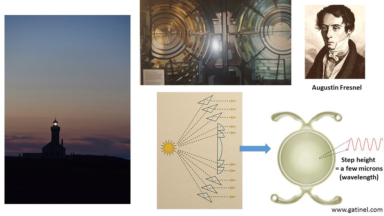
The profile of a multifocal diffractive IOL derives from the Fresnel zone plate.
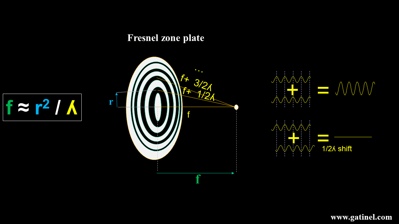
Zone plates are not efficient, mainly because they block part of the incident light. By applying Fermat’s principle, progressive modifications to the zone plate can be made to achieve higher efficiency and reduce the number of foci. The plate can be made transparent, and the blocking zones replaced by « phase-shifting » zones that selectively modify the optical path to cancel the half-wavelength phase shifts, allowing more light to interfere constructively at the desired focal distance. These zones look like little grooves, which can be made using microlithographic techniques on transparent lens materials. Before going further, it is important to review some theory and recall some important properties of diffractive IOLs. To understand how to achieve clinically efficient trifocality, it is mandatory to know the basic principles of diffraction for the realization of bifocal optics. At this stage, it is important to realize that diffractive elements are very sensitive to wavelength.
3.2 Basics of a Bifocal Diffractive IOL
Bifocality can be achieved by combining a conventional monofocal optic with a « kinoform zone plate, » whose profile results from applying Fermat’s principle (which states that light will always take the shortest path in time between two points). In gross approximation, the profile of the kinoform resembles that of an asymmetric « saw-tooth » profile. In practice, the height of these steps is on the order of a few microns. This is somewhat expected, as this scale is of the same order as that of the wavelength of incoming light (the visible light average wavelength is close to half of a micron, i.e., 500 nanometers).
3.3 Mathematical Design
(This section can be skipped by non-specialists) The phase shift created by a diffractive surface is proportional to the height h(r) of the surface profile and the wavelength of light λ. The equation governing the phase shift φ(r) at a radial distance r from the optical axis is given by:
φ(r) = 2π h(r) (n₂ – n₁) / λ
Where:
- h(r) is the height of the lens surface at radius r,
- n₁ and n₂ are the refractive indices of the surrounding medium and the IOL material, respectively,
- λ is the wavelength of light, typically 550 nm.
This equation forms the foundation for designing the diffractive profiles used in the FineVision IOL.
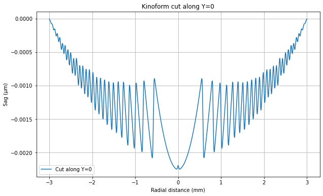
Kinoform Profile
The FineVision IOL leverages kinoform profiles, which are diffractive surfaces with continuous phase modulation. Kinoform profiles are designed to reduce the energy lost to higher diffraction orders, making them more efficient than traditional diffractive surfaces. The general equation for the height profile H(r) of a kinoform diffractive lens, as described in patent WO2011092169A1, is:
Where:
- a is the amplitude parameter specific to the lens design,
- R is the radial distance from the optical axis to the edge of the lens,
- λ is the wavelength of light,
- n₁ and n₂ are the refractive indices,
- F is the focal length associated with the diffractive order.
This equation looks rather complicated, but it explains the classic « saw-tooth » aspect of diffractive IOLs.
The FineVision IOL combines multiple such diffractive profiles to create a trifocal effect, balancing light between near, intermediate, and far distances.
Optical Design of the FineVision Trifocal IOL
Calculating Focal Lengths
In the FineVision IOL, the diffractive structure is designed to focus light at three distinct focal points: near, intermediate, and far. The focal lengths for near and intermediate vision are determined by the following vergence formula:
Where:
- P is the lens power in diopters,
- n₁ is the refractive index of the surrounding medium.
For a near vision power of +3.50D and an intermediate power of +1.75D, the focal lengths are calculated as follows:
- F₁ = 1.334 / 3.50 ≈ 0.3811 m (near focus)
- F₂ = 1.334 / 1.75 ≈ 0.7623 m (intermediate focus)
These focal lengths are used to design the diffractive profiles H₁(r) and H₂(r), which manage the light distribution to the near and intermediate foci, respectively.
Optimizing Light Distribution
The FineVision lens is designed to distribute light efficiently among the three focal points, allocating roughly 42% of light to far vision, 36% to near vision, and 22% to intermediate vision. This allocation ensures that patients can function across a wide range of activities without the need for additional corrective lenses. In addition to optimizing light distribution, the FineVision design also addresses chromatic aberrations by adjusting the height of the diffractive zones. This reduces chromatic aberration across varying lighting conditions, enhancing clarity at all distances.
3.4 General Properties of Kinoforms for Bifocal IOLs
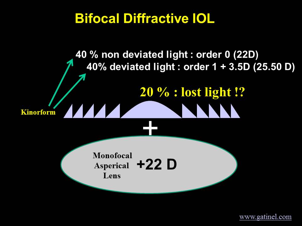
Here we will return to a simpler and more visual approach. The following illustration represents schematically the behavior of light waves diffracted through a kinoform.
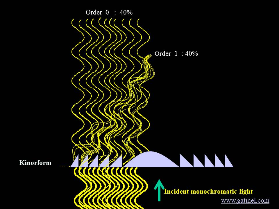
When properly designed, the kinoform can split incident light into several foci. This occurs when the optical path represented by the height of the steps is not an even multiple of the considered wavelength in the lens material. Some percentage of the incident light may not be deviated by the kinoform (0th order), while another percentage may go to the near focus (1st order). Some calculation shows that approximately 20% of incident light energy is diffracted in orders other than the 0th (non-deviated) and the 1st (near focus) when the kinoform is designed to be « bifocal » for a specific wavelength.
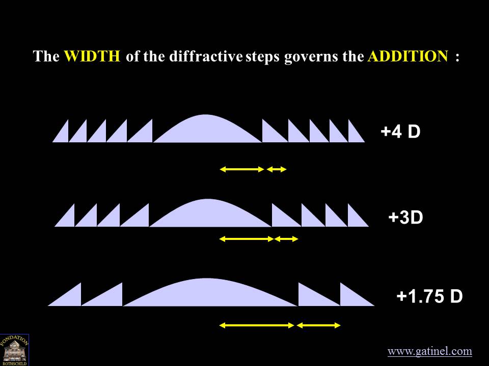
Effects of the Width of the Diffraction Steps
The width of the steps determines the distance at which the 1st (and subsequent) orders come into focus.
Apodization: Reducing the Height of the Diffractive Steps
The height of the steps is controlled by the design wavelength: optical designers may choose 550 nm, as it is the wavelength to which foveal (precise) vision is most sensitive. If the steps have a constant height value throughout the IOL, the distribution of incident light energy between the various diffraction orders will also be constant. A progressive reduction in step height can modulate the distribution of incoming light energy across the different diffraction orders as the pupil diameter increases. This reduction is called « apodization. »
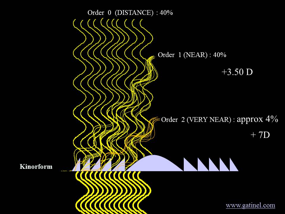
Vergence of Higher Diffractive Orders
It has been mentioned previously that the kinoform diffracts light into several orders beyond the 0th and the 1st order; these represent 20% of the initial light energy, provided 40% is diffracted toward the 1st order and another 40% is diffracted (but not optically deviated) toward the 0th order. The 0th order contributes to distance vision, the first order contributes to near vision, and the second and superior orders are lost for vision, as their vergences (the distance of the foci) are not useful.
Interestingly, with such a design, the second diffractive order has double the vergence of the first order.
4. Achieving Trifocality
The combination of two specific diffractive kinoform patterns makes the envisioned asymmetric distribution of light energy among the 3 foci possible.
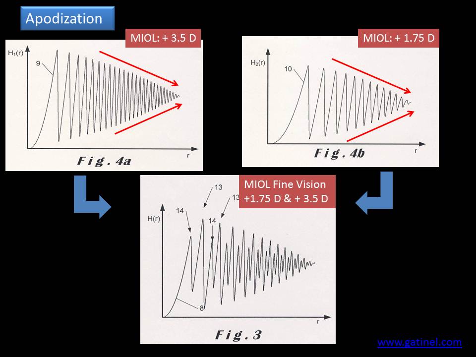
The final FineVision trifocal IOL profile (patented) is a combination of two apodized profiles. It displays a full diffractive area with a specific diffractive pattern comprising alternating diffractive steps of different heights.
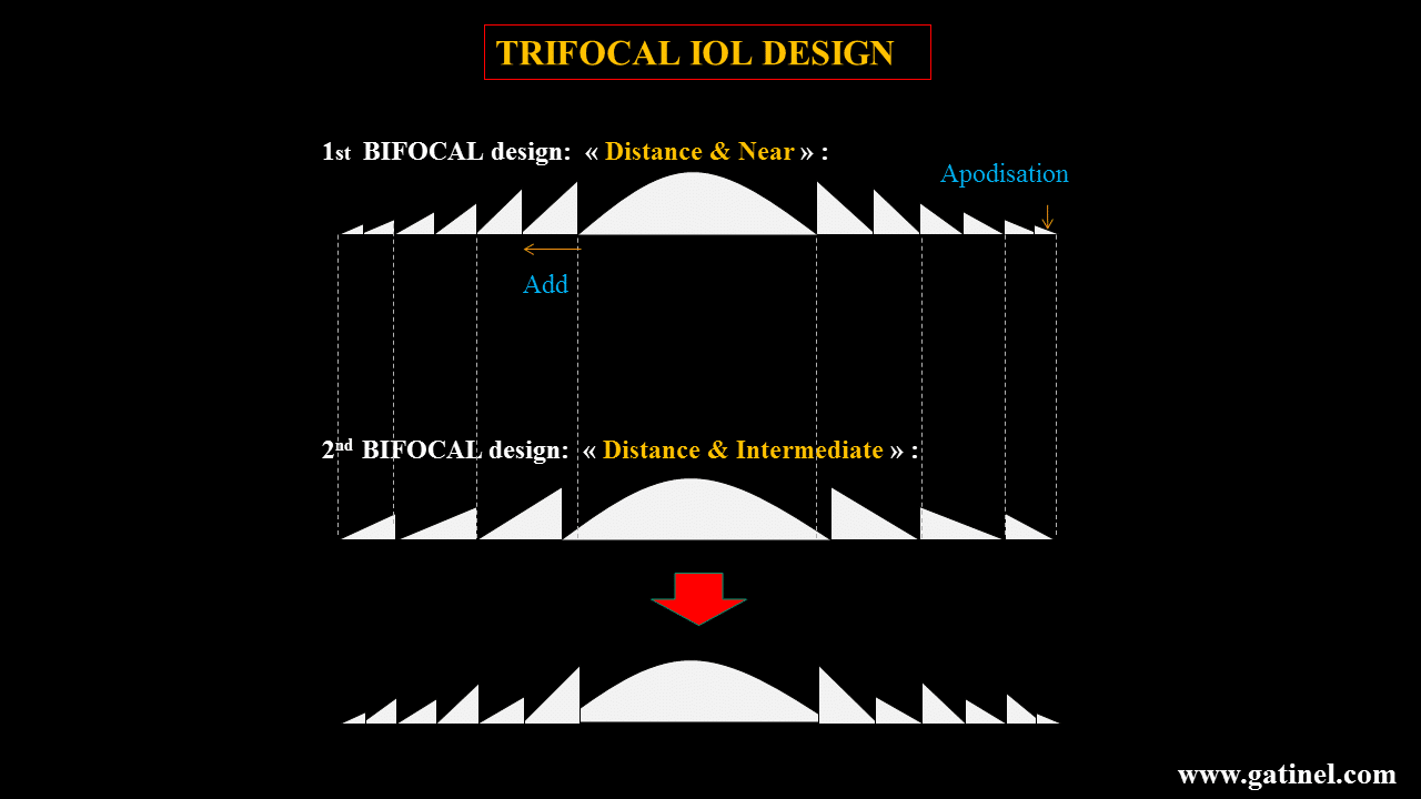
This diffractive area extends throughout the anterior side of the IOL. The zeroth (0th) order of the two profiles is used for far vision.
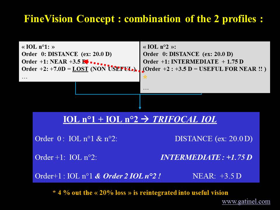
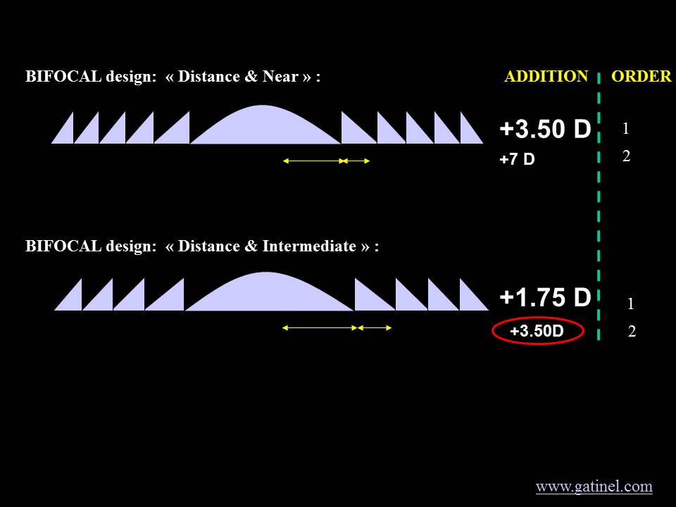
???? Key Innovation
In this innovative trifocal IOL design, the first kinoform pattern is designed with an addition of 3.5D as the first diffraction order. Therefore, the second diffraction order occurs at a vergence of 7D, which corresponds to lost light for useful vision. In contrast, the second kinoform pattern’s first order provides an addition of 1.75D (intermediate distance); hence, the second order has a vergence of 2 × 1.75 = 3.50D.
Therefore, the 2nd order of the second diffractive pattern is used to reinforce approximately 5% of near vision (Add +3.5D), which is mainly afforded by the first order of the first diffractive pattern. As a result, the energy loss, which is typically 20% for standard diffractive bifocal lenses, is reduced with this IOL to approximately 14%. The relative energy savings are approximately 25% compared with standard diffractive IOLs.
5. Apodization and Convolution
The IOL diffractive profile is also gradually attenuated throughout the entire optic (apodization), resulting in a continuous modulation of the light energy distribution directed to the three primary foci. The larger the considered zone, the more light is proportionally directed to the distance focus.
This profile is lathed on the surface of a monofocal aspherical optic. The asphericity of the monofocal lens is intended to optimize image quality by balancing physiological levels of corneal positive spherical aberration.
Apodization of the Trifocal Profile
As the step height decreases toward the periphery (apodization), the peripheral steps are progressively exposed as the pupil aperture becomes larger. This results in an increasing amount of light dedicated to the distance vision focus. Hence, less light is recruited for the near and intermediate focal points. This gradual decrease of the step height from center to periphery has been shown to reduce halos, which are generated by defocused light under dim conditions. In contrast to non-apodized IOLs, apodization provides some degree of customization for pupil movements: near reading tasks trigger pupil constriction, while mesopic distance vision (e.g., night driving) triggers pupil dilation. Apodization allows more light to be directed to the distance focus (0th order) when the pupil is dilated, thereby uncovering a larger IOL surface. This warrants superior optical performance in mesopic conditions.
Convolution of the Trifocal Profile
Diffraction can occur when light waves encounter any « abrupt » change in their path. The sharp edges of each step can cause unwanted diffraction, leading to a slight dispersion of incoming light energy. The light scattering on the edges of the steps can be decreased by their smoothing. Theoretically, this can be simulated by adding a mathematical smoothing function called « convolution. » This function was optimized to match the lens profile as manufactured, based on the cutting tool geometry, since in practice it is not possible to achieve abrupt steps with current lathing technology.
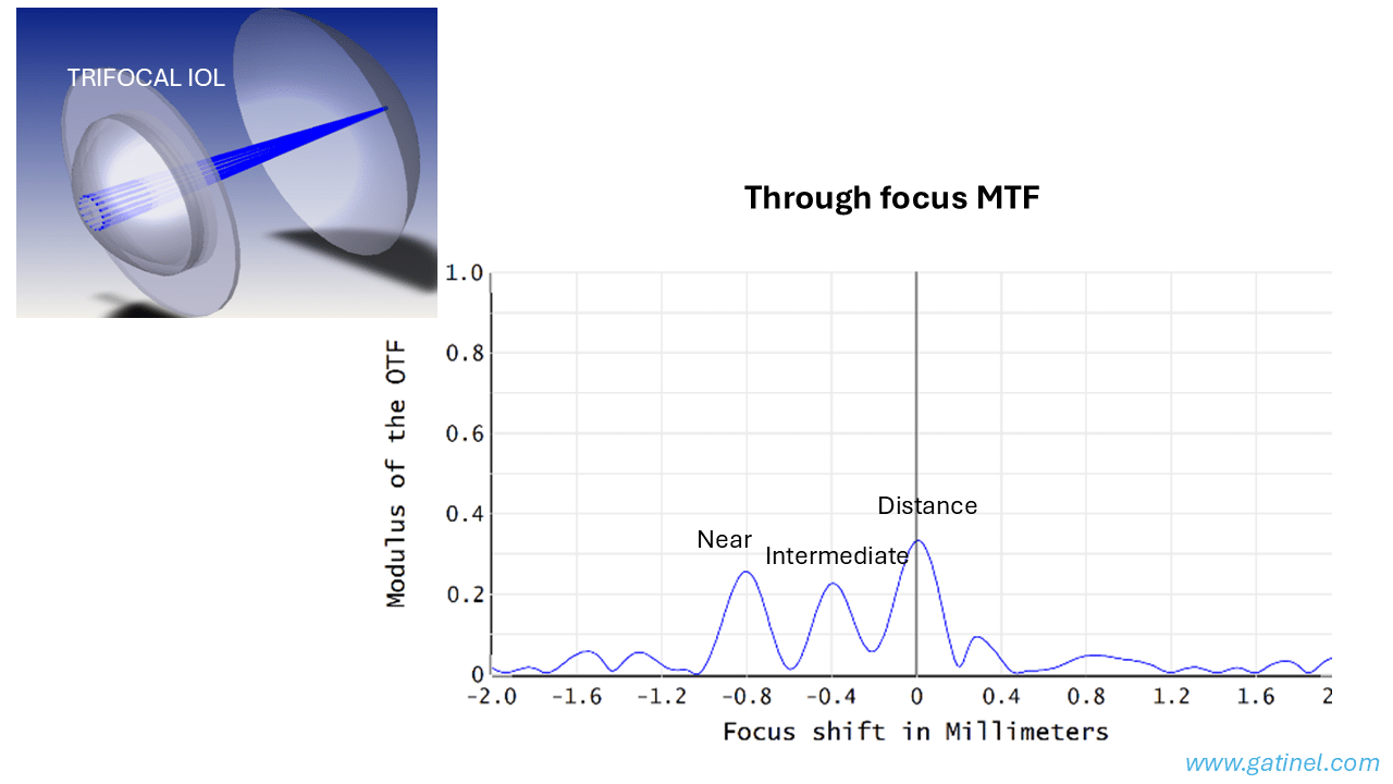
6. Optical Bench Results of the FineVision Trifocal IOL
The optical bench evaluation (through-focus and through-frequency MTF) has been conducted in accordance with ISO quality standards. These optical bench results echo the theoretical results. In addition to the two major foci at 0 and +3.5D, which provide add power for far and near vision, respectively, the FineVision multifocal IOL also provides a focus at +1.75D, which corresponds to intermediate vision. This characteristic should, therefore, offer enhanced visual performance for intermediate vision relative to that obtained by conventional bifocal multifocal IOLs.
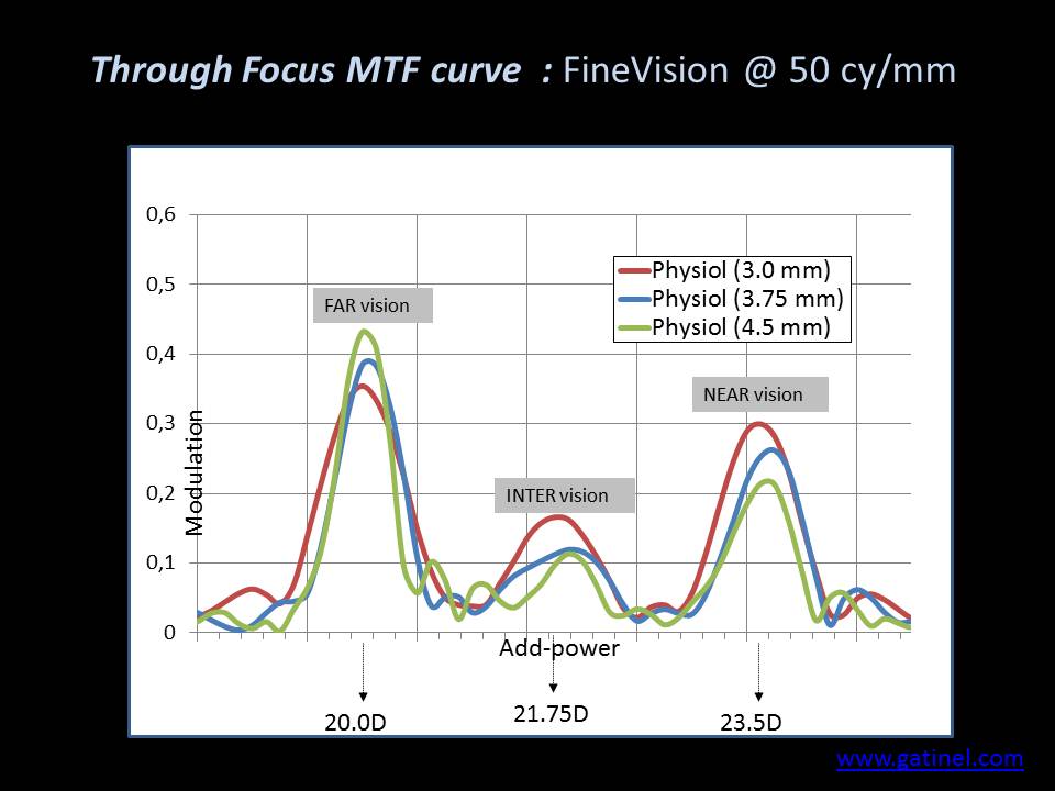
The diffractive profile test has been designed to extend throughout the entire optical surface of the FineVision trifocal IOL. The gradual decrease in step height toward the periphery reinforces distance vision under mesopic conditions, when human pupils dilate. Without this gradual reduction, the contribution to far, intermediate, and near vision would be constant across the entire optical surface for any pupil size: this would not be optimal as all human pupils tend to dilate when ambient light reduces and to constrict when attempting to perform near visual tasks such as reading. The variations of the through-focus MTF curve of the IOL for different pupil apertures confirm that the FineVision IOL is pupil-dependent and designed to favor distance vision under dim light conditions. This change of energy balance with pupil size mimics the natural pupil’s response to various lighting conditions. It is a function of the required distance (near or far vision). It is consistent with the accommodation reflex, in which the pupil tends to constrict for near vision. To decrease the risk of glare at night, only 9% of the energy is devoted to intermediate vision at a 4.5 mm pupil aperture. The FineVision Physiol trifocal IOL was the first IOL ever designed to display a useful additional focus for intermediate vision at +1.75D. This IOL improves intermediate vision relative to standard bifocal IOLs while maintaining near and far visual performance owing to its advanced optical features: apodization, convolution, and aspherization. The risk (for the patient) associated with this intermediate focus seems limited relative to the offered benefit, as the diffractive structure of this trifocal IOL was designed to allocate less energy to intermediate vision than to far and near vision. Regardless of pupil size, the limited energy allocated to intermediate vision reduces the risk of monocular diplopia at intermediate focus.
7. Current Trifocal IOL Market (2024-2025)
Since the introduction of the first trifocal IOL (FineVision) in 2010, several manufacturers have developed their own trifocal designs. The current market includes:
| IOL Model | Manufacturer | Add Powers | Design | Material |
|---|---|---|---|---|
| FineVision HP | BVI (formerly PhysIOL) | +1.75D / +3.50D | Diffractive, apodized | Hydrophobic acrylic |
| AcrySof IQ PanOptix | Alcon | +2.17D / +3.25D | Diffractive, non-apodized (4.5mm) | Hydrophobic acrylic |
| AT LISA tri 839MP | Carl Zeiss Meditec | +1.66D / +3.33D | Diffractive, non-apodized | Hydrophilic acrylic |
| TECNIS Synergy | Johnson & Johnson Vision | Continuous | Diffractive + EDOF | Hydrophobic acrylic |
| FineVision Triumf | BVI | +1.75D / +3.50D | Diffractive, chromatic correction | Hydrophobic acrylic |
???? Clinical Outcomes Summary (2019-2024)
A comprehensive literature review published in Frontiers in Medicine (2025) analyzed 18 clinical studies including 1,028 eyes implanted with the FineVision HP IOL:
- Spectacle independence: 82-96% of patients report complete spectacle independence
- Distance UDVA: Mean 0.02 to 0.08 logMAR
- Intermediate UIVA (60-80 cm): Mean 0.05 to 0.15 logMAR
- Near UNVA (40 cm): Mean 0.02 to 0.10 logMAR
- Patient satisfaction: >95% in most studies
- Dysphotopsia: Halos reported by 15-30% of patients, rarely « bothersome »
Source: Ristvedt D, Bosc C, Thompson V. Front Med. 2025;12:1533161.
8. Trifocal vs. EDOF IOLs: Superior Near Vision
Extended Depth of Focus (EDOF) IOLs represent an alternative approach to presbyopia correction. Unlike trifocal IOLs that create three distinct focal points, EDOF lenses produce a single elongated focal zone, aiming to provide continuous vision from distance to intermediate without the « peaks and valleys » of traditional multifocal designs. While this approach may reduce photic phenomena (halos, glare), clinical evidence consistently demonstrates that trifocal IOLs provide significantly better near vision than EDOF lenses.
⚖️ Meta-Analysis Results: Trifocal vs. EDOF (22 Studies, 2,200 Eyes)
A comprehensive meta-analysis published in the American Journal of Ophthalmology (2023) comparing trifocal and EDOF IOLs found:
- Uncorrected Near Visual Acuity (UNVA): Significantly better with trifocal IOLs (p < 0.00001)
- Distance-Corrected Near Visual Acuity (DCNVA): Significantly better with trifocal IOLs (p = 0.002)
- Spectacle Independence: 88% for trifocal vs. 52% for EDOF for near tasks
- Distance and Intermediate Vision: No significant difference between groups
- Halos and Glare: No significant difference between groups
- Quality of Vision Score: Better with trifocal IOLs (p = 0.03)
Source: Karam M et al. Am J Ophthalmol. 2023;251:52-70.
Key Differences Explained
The fundamental difference lies in the optical design philosophy:
| Characteristic | Trifocal IOLs | EDOF IOLs |
|---|---|---|
| Optical Design | Three distinct focal points | Single elongated focal zone |
| Near Addition | +3.25D to +3.50D | +1.50D to +1.75D |
| Near Focus Distance | ~40 cm (reading) | ~55-60 cm (limited) |
| Reading Ability | Excellent (books, phone) | Limited (may need glasses) |
| Spectacle Independence (Near) | ~88% | ~52% |
| Intermediate Vision | Good (60-80 cm) | Good to excellent |
Clinical Implications
For patients who prioritize reading and close-up tasks (smartphones, books, detailed work), trifocal IOLs remain the better choice. The higher near addition power (+3.25D to +3.50D) provides a true near focus at typical reading distances (35-40 cm), whereas EDOF lenses with their lower addition (+1.50D to +1.75D) may leave patients dependent on reading glasses for fine print. As noted at the ESCRS Winter Meeting debates, « There is no ideal IOL. However, EDOF lenses have the advantage in intermediate vision, while trifocals clearly excel in near vision. » The choice should be individualized based on the patient’s lifestyle and visual priorities.
9. Online IOL Simulation: AIOL Sci
Today, IOL power formulas are well established. The real challenge comes after power selection: how do you decide which IOL design will benefit your patient the most? In an industry full of players competing for attention, there is now an objective, patient-specific way to answer that question. AIOL Sci bridges lab physics and clinical decision-making by combining measured IOL wavefronts with a personalized aspheric cornea model (R, Q). The platform computes through-focus MTF to quantify how a specific IOL will perform in your patient’s eye—not in an average eye.
???? AIOL Sci: Patient-Specific IOL Optical Simulation
aiolsci.com is the first online platform providing objective, manufacturer-independent data on lens performance, transformed into patient-specific visual outcome predictions:
- Empirical IOL data: Lens catalogue built entirely on proprietary optical bench measurements—capturing real optical effects including asphericity, refractive profiles, diffractive steps, and manufacturing tolerances
- Patient-specific corneal modeling: Adjustable corneal radius (R) and asphericity (Q) to simulate your actual patient’s optics
- Through-focus MTF: Reports at multiple spatial frequencies (10, 30, 50, 100 lp/mm) and pupil sizes (3.0 mm, 4.5 mm)
- Direct design comparisons: Evaluate monofocal, enhanced monofocal, EDOF, and trifocal IOLs side-by-side for the same eye
- Manufacturer-neutral: Works with any biometer or topographer, no hardware lock-in
➡️ Visit: https://aiolsci.com
Why Patient-Specific Simulation Matters
Every eye is unique. Corneal curvature (K) and asphericity (Q) govern spherical aberration, which can reshape through-focus image quality dramatically. Standard models assume an « average » cornea, but this leads to suboptimal outcomes—especially after refractive surgery, where aberrations shift significantly. AIOL Sci enables you to model potential IOL selections for each patient’s corneal optics, for modern, personalized care. Choosing a lens without considering the cornea’s actual optics is like tailoring a suit without measurements: it may look fine on paper, but it fails in practice.
Empirical IOL Data vs. Manufacturer Datasheets
The AIOL Sci lens catalogue is built entirely on proprietary optical bench measurements. Using a validated method, the platform captures the true optical effects of each IOL model, including asphericity, refractive profiles, diffractive steps, and manufacturing tolerances and defects. This ensures that the simulator reflects the true manufactured performance of the lens—not the idealized design described in marketing datasheets.
Manufacturer-Neutral & Device-Agnostic
AIOL Sci works seamlessly with any commonly available biometers and topographers, without locking users into a specific hardware platform or IOL manufacturer. The expanding IOL library spans multiple manufacturers, giving you the flexibility to balance performance and cost transparently. The platform provides objective, manufacturer-independent data on lens performance, transformed into patient-specific visual outcome predictions. Results are delivered in plain language and intuitive graphics, focusing on what matters most in the clinic: clarity at distance and near, and the depth of field that a given lens delivers in that individual eye.
What You See
AIOL Sci reports through-focus Modulation Transfer Function (TF-MTF) at several spatial frequencies (10, 30, 50, 100 lp/mm and average) at common pupil sizes (3.0 mm and 4.5 mm). These outputs make it clear how contrast shifts across focus, enabling:
- Contrast curves that condense performance into an easy-to-interpret metric
- In vitro depth of field estimates based on published thresholds
- Direct design comparisons so you can evaluate different monofocal, EDOF, and multifocal options side by side for the same eye
Why It Matters
The number of available IOL designs continues to grow, while patient expectations are higher than ever. The expanding range of options—enhanced monofocals, EDOF, multifocals, and novel profiles—makes apples-to-apples comparisons difficult. Bench-measured metrics such as standardized MTF at 50 lp/mm or TF-MTF curves published by manufacturers on an « average cornea » provide useful reference points, but they only describe average performance. By combining bench-measured IOL optics with patient-specific corneal modeling, AIOL Sci equips surgeons with an intuitive, science-based foundation for lens selection—ensuring each IOL choice is tailored to the individual patient rather than the statistical mean.
???? Built by Surgeons, for Surgeons
The AIOL Sci platform was designed by cataract surgeons who experienced these challenges first-hand. By combining bench-measured IOL optics with patient-specific corneal modeling, it equips surgeons with an intuitive, science-based foundation for lens selection—ensuring each IOL choice is tailored to the individual patient rather than the statistical mean. Results are delivered in plain language and intuitive graphics, focusing on what matters most in clinic: clarity at distance and near, and the depth of field that a given lens delivers in that individual eye.
10. References
Original Publications (Gatinel et al.)
- Gatinel D, Pagnoulle C, Houbrechts Y, Gobin L. Design and qualification of a diffractive trifocal optical profile for intraocular lenses. J Cataract Refract Surg. 2011;37(11):2060-2067. PMID: 22018368
- Gatinel D, Houbrechts Y. Comparison of bifocal and trifocal diffractive and refractive intraocular lenses using an optical bench. J Cataract Refract Surg. 2013;39(7):1093-1099. PMID: 23692884
- Cochener B, Vryghem J, Rozot P, Lesieur G, Chevalier JP, Henry JM, David T, Lesueur L, Gatinel D, et al. Clinical outcomes with a trifocal intraocular lens: a multicenter study. J Refract Surg. 2014;30(11):762-768. PMID: 25375849
- Cochener B, Vryghem J, Rozot P, et al. Visual and refractive outcomes after implantation of a fully diffractive trifocal lens. Clin Ophthalmol. 2012;6:1421-1427. PMID: 23055669
Recent Clinical Studies (2023-2025)
- Ristvedt D, Bosc C, Thompson V. Clinical outcomes of a hydrophobic trifocal diffractive intraocular lens: a literature review. Front Med. 2025;12:1533161. doi: 10.3389/fmed.2025.1533161
- Łabuz G, Varadi D, Khoramnia R, Auffarth GU. A Comparative Analysis of the Effects of Misaligning Different Trifocal Intraocular Lenses. J Clin Med. 2025;14(1):187. doi: 10.3390/jcm14010187
- Malyugin B, Fomina O, Sobolev N, et al. Visual results and subjective satisfaction after implantation of two different trifocal diffractive intraocular lenses models (AcrySof IQ PanOptix and AT LISA tri 839 MP). Eur J Ophthalmol. 2024;34(3):726-733. PMID: 37770020
- Yilmaz IE, Berhuni M, Öztürkmen C, et al. Focusing on the Future: Patient-Centered Insights into Trifocal Intraocular Lens Adoption. Klin Monbl Augenheilkd. 2025;81:1-6. PMID: 40125784
- Ribeiro FJ, Ferreira TB. Comparison of clinical outcomes of 3 trifocal IOLs. J Cataract Refract Surg. 2020;46(9):1247-1252. PMID: 32898095
- Łabuz G, Auffarth GU, Khoramnia R, et al. Trifocal Intraocular Lens Selection: Predicting Visual Function From Optical Quality Measurements. J Refract Surg. 2023;39(2):94-101. PMID: 36799519
Review Articles and Meta-Analyses
- Vargas V, Alió JL. Multifocal Intraocular Lenses: FineVision (PhysIOL) Lens. In: Alió J, Pikkel J (eds). Multifocal Intraocular Lenses. Springer, 2019. doi: 10.1007/978-3-030-21282-7_22
- Karam M, Alkhowaiter N, Alkhabbaz A, et al. Extended Depth of Focus Versus Trifocal for Intraocular Lens Implantation: An Updated Systematic Review and Meta-Analysis. Am J Ophthalmol. 2023;251:52-70. PMID: 36736751
- Bosc C, Alió Del Barrio JL, Souied E, et al. Clinical outcomes of trifocal toric intraocular lenses. J Cataract Refract Surg. 2023;49(3):328-338. PMID: 36788496
Patents
- Gatinel D, Pagnoulle C. Diffractive trifocal lens. Patent WO2011092169A1. Filed January 2010, published August 2011.
See also: Cataract Surgery | IOL Power Calculation | PresbyopiaPage updated: January 2026
Laisser un commentaire