Aberrations post presby-LASIK
This clinical case provides a classic example of the limitations of the Zernike series to characterize the typical deformation of the ocular wavefront after LASIK surgery of hyperopia and presbyopia (« presby-LASIK »). Although the concept of using higher order aberrations such as negative spherical aberration to increase the ocular multifocality is well accepted, there has been some confusion regarding the impact of this method on the refractive status of the eye.
As this example and others clearly demonstrates, Zernike spherical aberration is not purely a higher order aberration and its presence dramatically affects the refractive status of the eye.
Our novel LD-HD method allows to better quantify and qualify the typical low and higher order aberrations of an eye in such clinical scenario.
All calculations were made using a pioneer software upgrade installed on the topographer & wavefront sensor Nidek OPD-Scan III.
Refraction and vergence map
Some aberrometers, such as the OPD scan III (Nidek, Japan), enables us to plot the local variations of refractive errors in a vergence map called the “OPD map”. It allows the visualization of the local variations of the refractive error (vergence) across the entrance pupil area in the eye of interest.
In the presented example, the OPD map was obtained 2 months after a “presbyLASIK” procedure was conducted , which aimed to correct a preoperative hyperopia of +1.50 D and presbyopia in a 57 yo patient. (read more about the theoretical framework of custom Q aspheric ablation for the correction of hyperopia and presbyopia)
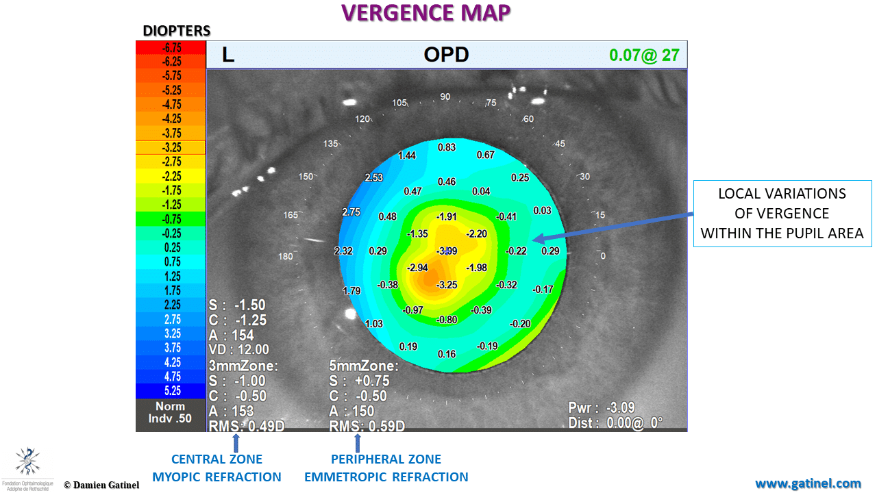
Vergence map of an eye operated with an aspheric profile of ablation aiming at inducing a « multifocal » refraction, characterized by a central island of myopic refraction, surrounded by an annulus of emmetropia.
The increase in the curvature of the central part of the cornea has resulted in a myopic shift – best corrected visual acuity was 20/20 with a -1.50 / -1 D x 155° correction. The patient can read Jaeger 2 without any optical aid with the left eye. Due to a relative reduction of the myopic error towards the pupil edge, uncorrected distance visual acuity was 20/30 with the same eye.
The presence of a concentric gradient of power between the center and the periphery of the pupil refers to the ocular spherical aberration, that is the difference between the refractive powers of the center and the edge of the functional pupil. It seems important that a wavefront description using a series of coefficients can accurately describe the optical status of an eye such as this / of an eye in this clinical scenario.
(more about presbyLASIK strategies based on the manipulation of corneal asphericity:
In the Zernike classification Z40 is the symbol for spherical aberration, which is weighted by a coefficient z40, whose value is expressed in micron units and refers to a specific pupil diameter.
The Zernike spherical aberration contains some « defocus » (low degree) which is myopic for negative spherical aberration and hyperopic for positive spherical aberration. When mentioning Z40 one usually refers to the true « higher degree » component (term in r^4, that is in the fourth power of the radial distance to the center of the pupil).
This higher order term modulates the refraction significantly within the pupil toward the periphery : increased hyperopia/ decreased myopia for negative spherical aberration.
When the refractive power (vergence) is higher at the pupil center than its periphery, spherical aberration is said to be negative (c40 <0).
When the refractive power is lower at the pupil center than its periphery, the spherical aberration is said to be positive (c40 >0).
Increasing the amount of spherical aberration can increase the eye’s multifocality to improve the ability to form retinal images of nearer and farther image targets with reasonable sharpness. For combined hyperopic and presbyopic corrections, it is common to reverse the natural spherical aberration of the eye, which is slightly myopic.
Inducing negative spherical aberration aims at inducing some myopic defocus at the center of the pupil and reducing some myopic defocus towards the pupil periphery.
In such a situation, the eye would be best refracted for distance with a negative spectacle correction, and hence can be considered as myopic. However, its uncorrected distance acuity would exceed that of an eye where the whole pupil area (paraxial and paracentral zone) would both be equivalently myopic. The less myopic (or closer to emmetropia) paracentral pupil zone provides the eye with improved uncorrected distance visual acuity.
It is thus important to keep in mind that in order to provide the operated eye with efficient multifocality, negative spherical aberration must be accompanied by selective central pupil myopia.
Corneal topography
The corneal profile of the human eye has negative asphericity; its curvature decreases from the apex toward the periphery; this topographic property is named “prolateness”. A mathematical variable, named “Q”, can quantify the level of asphericity of the corneal contour modeled as a conic section (e.g. ellipse). A negative Q-value characterizes a prolate cornea.
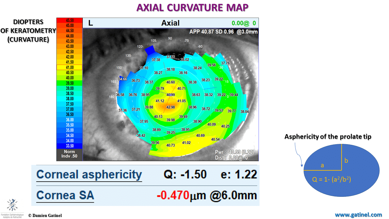
Axial curvature topography map (expressed in keratometric diopters)
A change in corneal asphericity (ΔQ) can induce a variation in spherical aberration of Δc40 on a specific zone.
We have addressed via theoretical modelling the relationship between the corneal asphericity and the subsequent variations in Zernike spherical aberration in 2014 in a publication in the Journal of Refractive Surgery. In this case, a special “aspheric” profile was delivered during a femto LASIK procedure. It aimed to make the center of the optical zone myopic, and its peripheral zone less myopic or as close to emmetropia as possible.
In our clinical example, the Q value is very negative and corresponds to a marked prolateness (comparable to that of a hyperbolic surface). Consequently, the corneal spherical aberration is reversed to a negative value.
It may now be particularly interesting to compare the ocular wavefront coefficients obtained via Zernike vs the novel LD-HD method.
Low order wavefront components
There are tremendous difference between the higher order wavefront obtained using the Zernike vs LD-HD decomposition method.
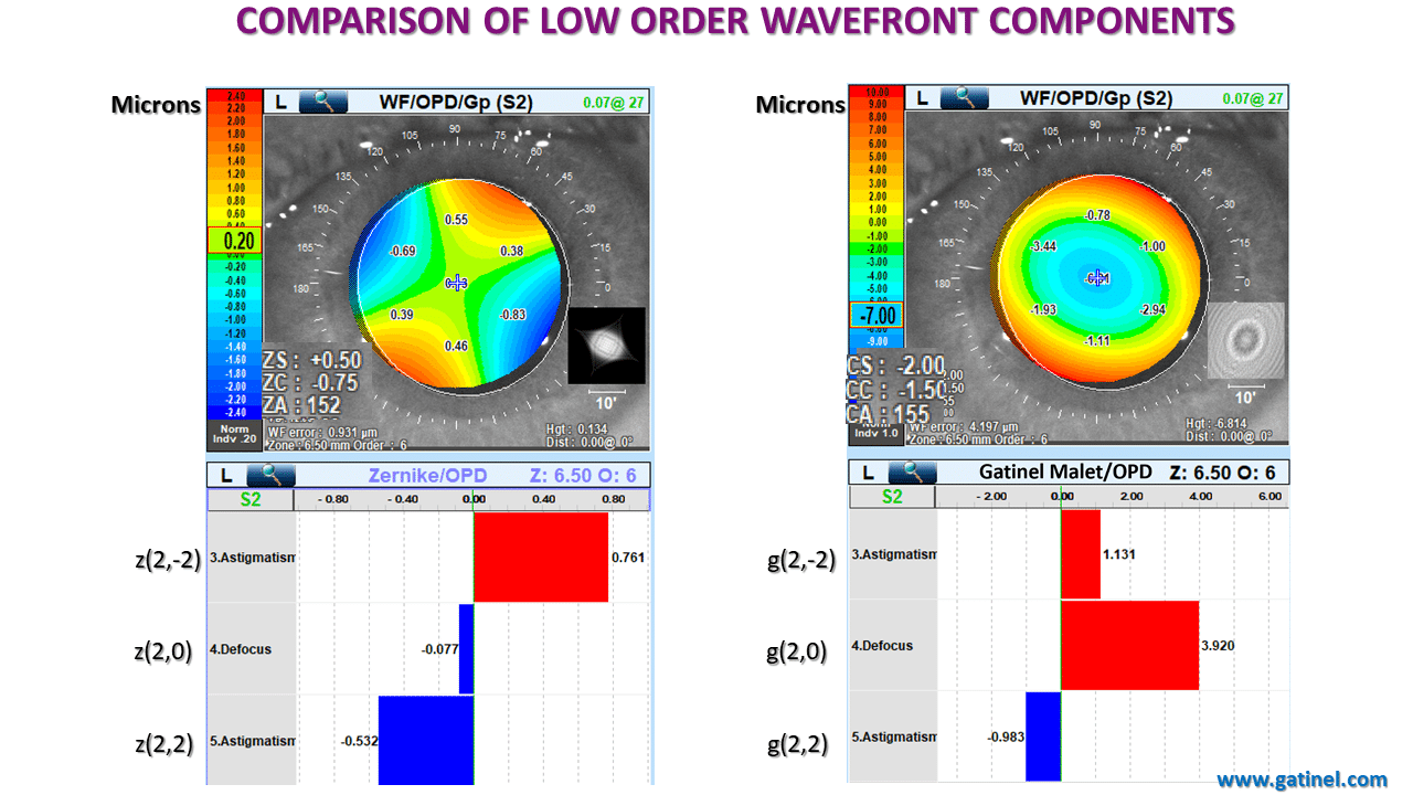
Zernike vs Gatinel Malet coefficients of the 2nd radia degree (low order) and their predicted refraction.
The lower order wavefront aberration components exhibit dramatic differences. The refraction predicted from the LD-HD method is myopic and closer to the subjective refraction of the patient. On the contrary, the Zernike predicted refraction is close to emmetropia, and even slightly hyperopic!
Higher order wavefront components
Large differences between low order wavefront component estimations logically leads to tremendous a significant difference between the higher order wavefront obtained using the Zernike vs LD-HD decomposition method:
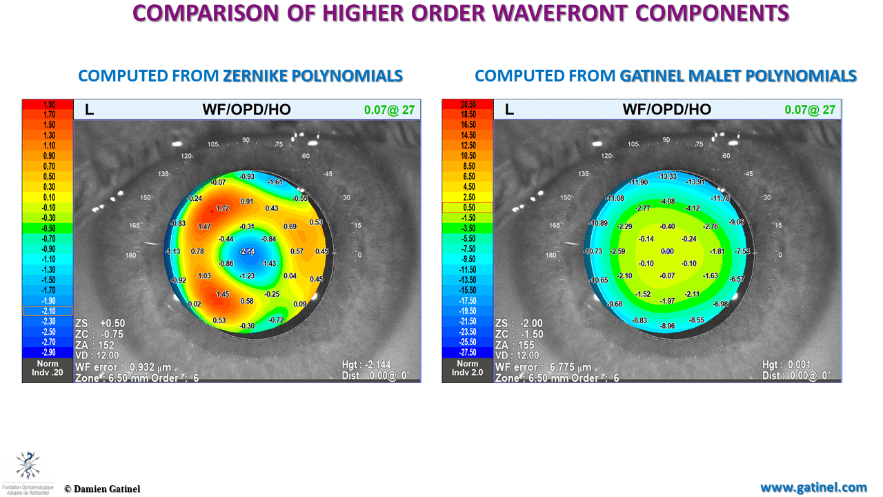
Comparison between the surfaces of the higher order aberration surface obtained with the Zernike vs LD-HD method.
The Zernike HO wavefront surface exhibits a “sombrero” shape with a marked central trough. This rapid wavefront phase variation within the central pupil zone must impact the refraction significantly, whereas the higher order wavefront component should not. The LD-HD wavefront surface is flat paraxially, and exhibits a progressive negative phase shift toward the periphery.
Higher order wavefront Zernike coefficients
This is the Zernike coefficients bar chart. The highest coefficient is vertical tilt. The defocus (z20) is null. Negative spherical aberration is the largest higher order coefficient, and exhibits a negative sign.
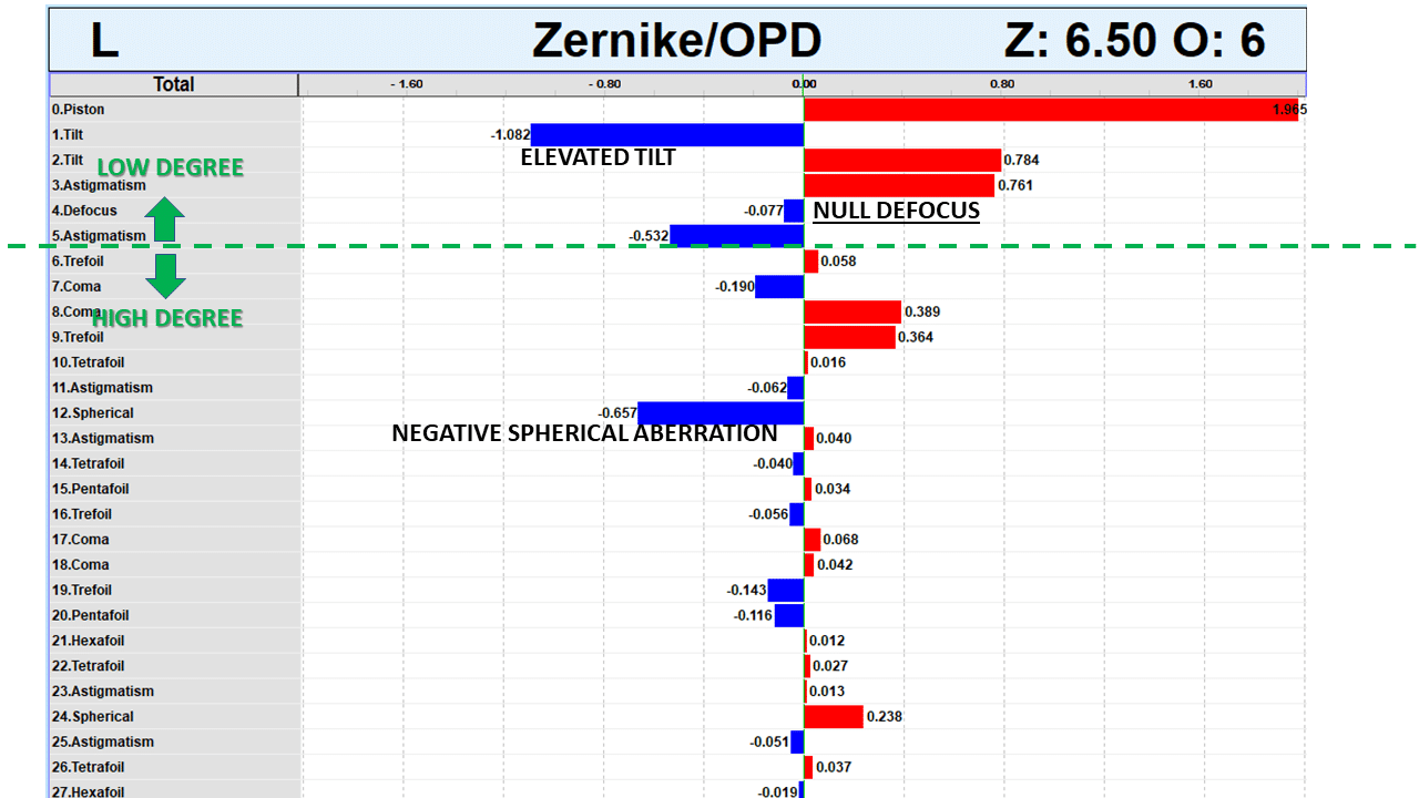
Zernike coefficients (6.50 mm pupil)
Higher order wavefront Gatinel Malet coefficients
In the LD-HD wavefront decomposition in with Gatinel Malet coefficients, the tilt is negligible, whilst a significant myopic defocus is present. The increase in negative spherical aberration coefficient is impressive!
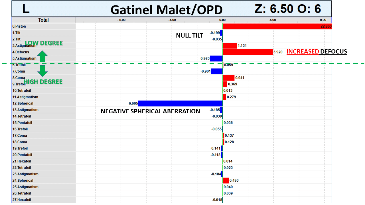
Gatinel Malet coefficients (6.50 mm pupil)
Direct comparison between wavefront coefficients
To better apprehend the difference in coefficients magnitudes in the two decompositions, they are here presented here side by side:
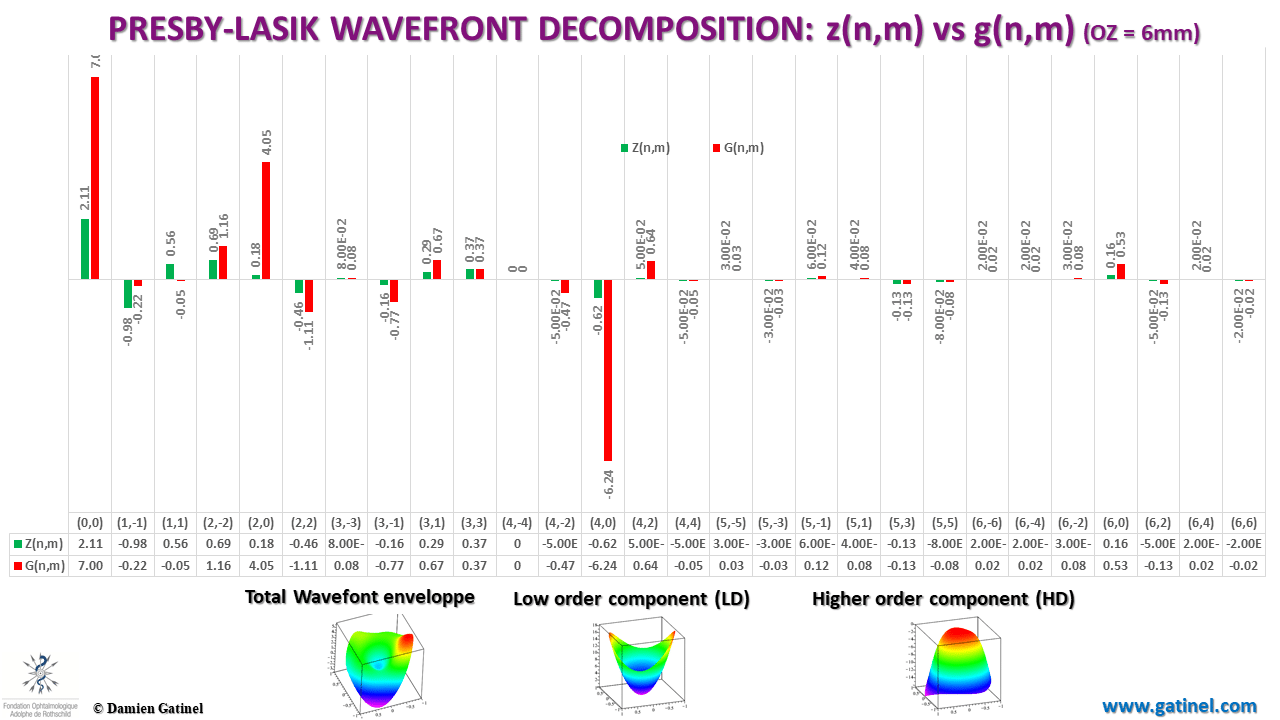
Comparison between the magnitudes of the Zernike vs Gatinel Malet wavefront coefficients (6 mm pupil)
The hidden defocus in Zernike spherical aberration
Explaining these striking differences is simple when one realizes that the Zernike spherical aberration mode is not pure in r^4 but contains large amount of defocus (r^2). In our clinical example, the total defocus contained this « hidden » defocus.
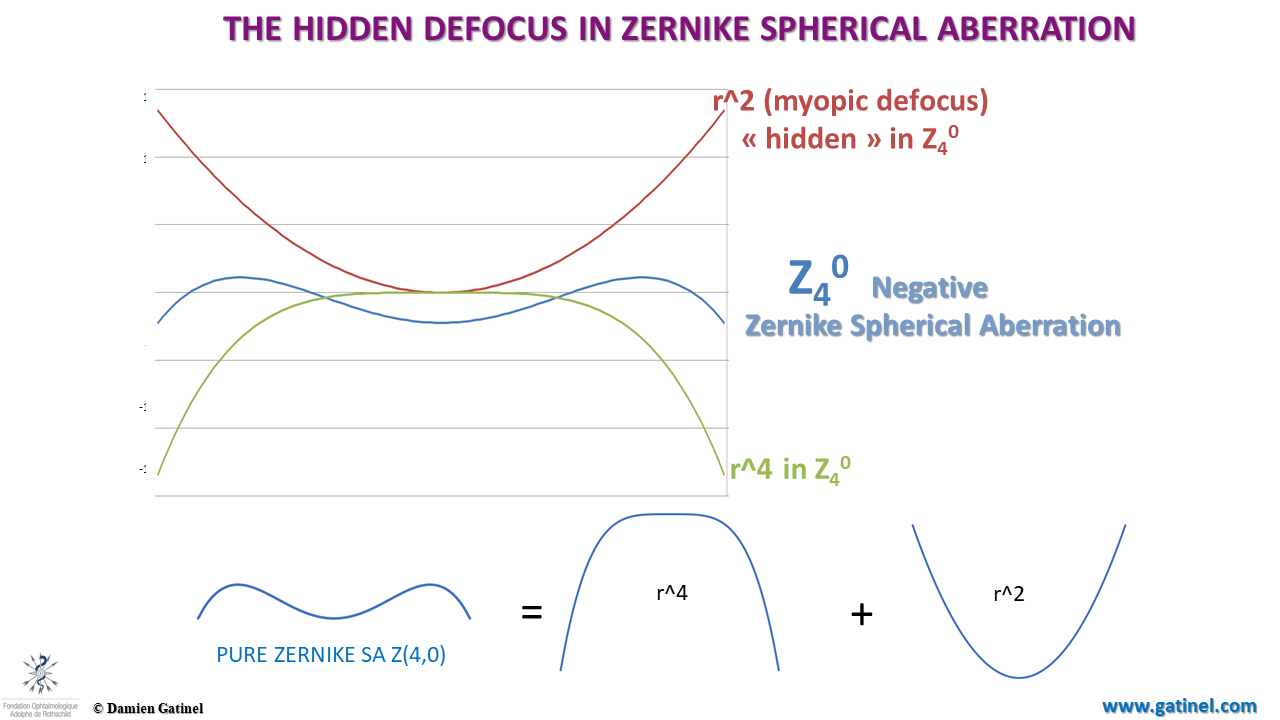
Cross-section depiction of the decomposition of a negative Zernike spherical aberration mode wavefront surface ( Z40) into it’s pure r^2 and r^4 phase term errors (equivalent to Seidel modes).
Vectorial depiction
This vector chart allows to visualize the differences between the decomposition. Note the orthogonality between the lower vs higher order Zernike components, and the absence of orthogonality between the lower vs higher order LD-HD component:
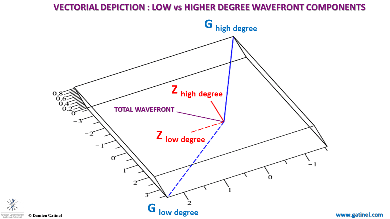
Low and high components of the total wavefront in the Zernike vs LD-HD decomposition.
This vector plots shows the decomposition of the higher order Zernike vs LD-HD components (Zhd) between the 3rd, 4th and higher (5 and 6th) components. Because of some artifacts in the Zernike coefficients, the magnitude of the 4th order component is artificially reduced in the Zernike decomposition:
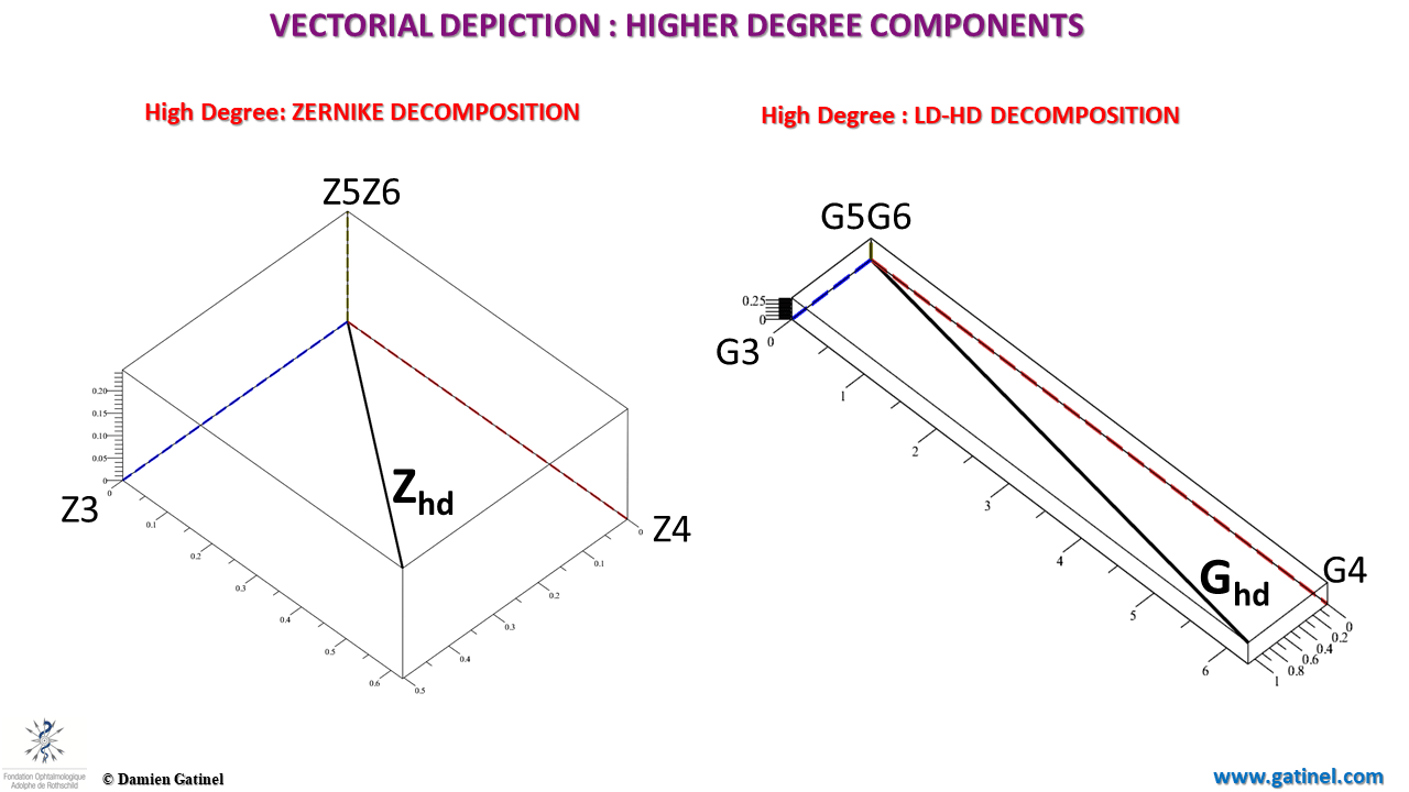
Decomposition in 3rd, 4th and (5+6)th order of the higher order wavefront in the Zernike vs HD space.
Point Spread Functions
The point spread function (PSF) is computed via Fourier optics, as the response of an imaging system to a point source or point object.
In an ideal optical system, the PSF is a bright spot surrounded by some faint diffraction halos. Contrarily, an eye with aberration does not concentrate the beam into a small bright point, resulting in a spread of the light energy.
The Strehl ratio is proportional to the amount of light which is focused within the main peak of the PSF. It has a value between 0 and 1. A perfectly unaberrated eye (or optical system) has a Strehl ratio of 1.
In our case, the higher order Point Spread Function (HO-PSF) computed from the Zernike coefficients and modes seems affected by large amounts of defocus.
The PSF computed from the HO Gatinel Malet coefficients better reflects the impact of the pure higher order wavefront errors, which spread the light in the form of a central bright light peak.
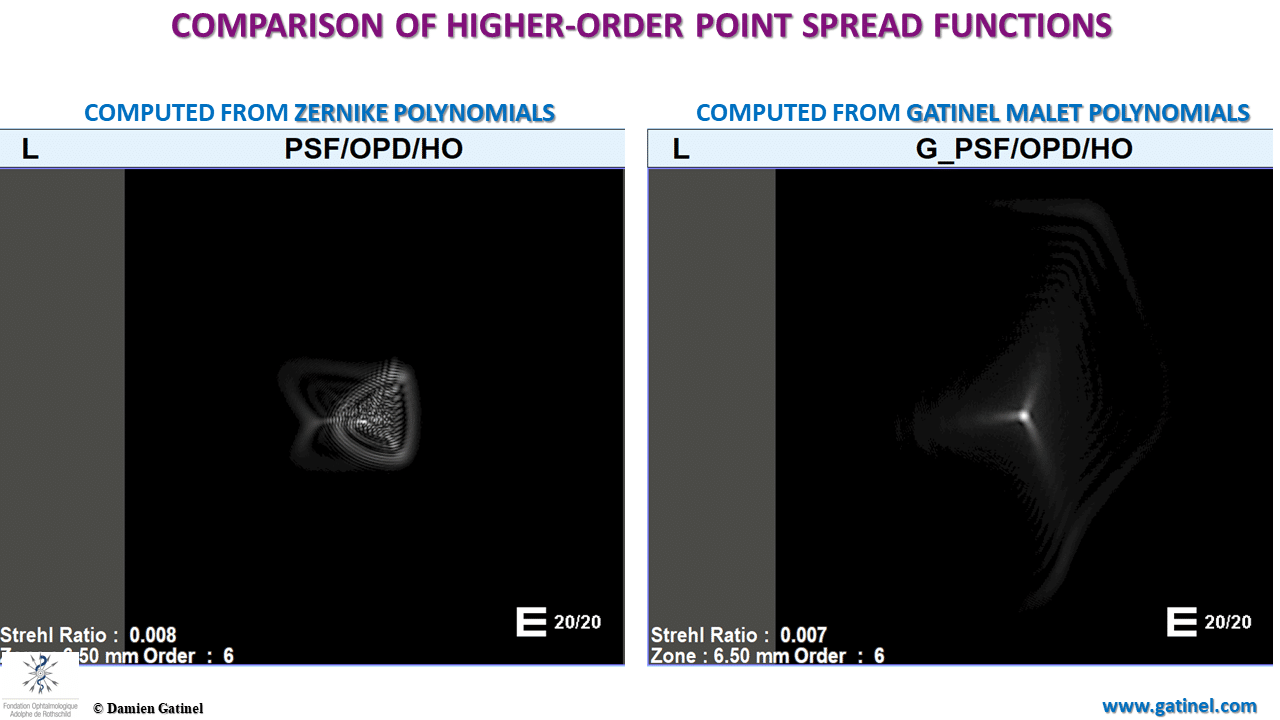
Comparison of the higher order Point Spread Functions.
Visual acuity chart simulations
From the HO-PSF computation, it is possible to display the predicted retinal image of a visual acuity chart for the best spectacle correction (this is achieved via the convolution of the reference image with the HO-PSF).
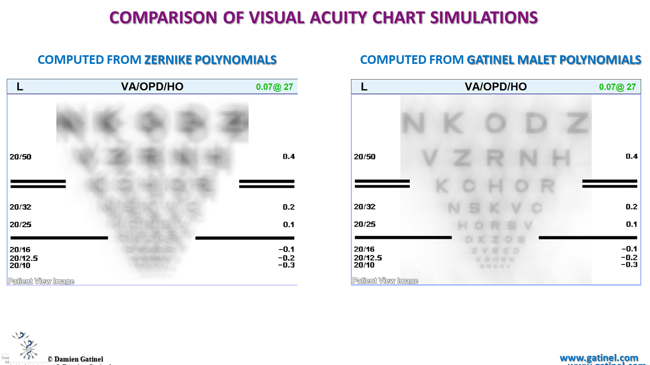
Comparison between the retinal images for the best spectacle correction (the image degradation is caused by the higher order wavefront component).
The Zernike higher-order visual acuity (for the best spectacle correction) is underestimated. This is because of the presence of the defocus term within the analytical expression of the Zernike spherical aberration mode.
In the LD-HD decomposition, the visual acuity corresponds to the clinical performance of the examined eye: seen here as a marked loss of contrast sensitivity but with conservation of >20/20 on the visual acuity chart.
Modulation Transfer Functions
For the same reasons, the MTF computed from the HO Zernike coefficients and modes overestimates the contrast sensitivity loss and cut-off frequency:
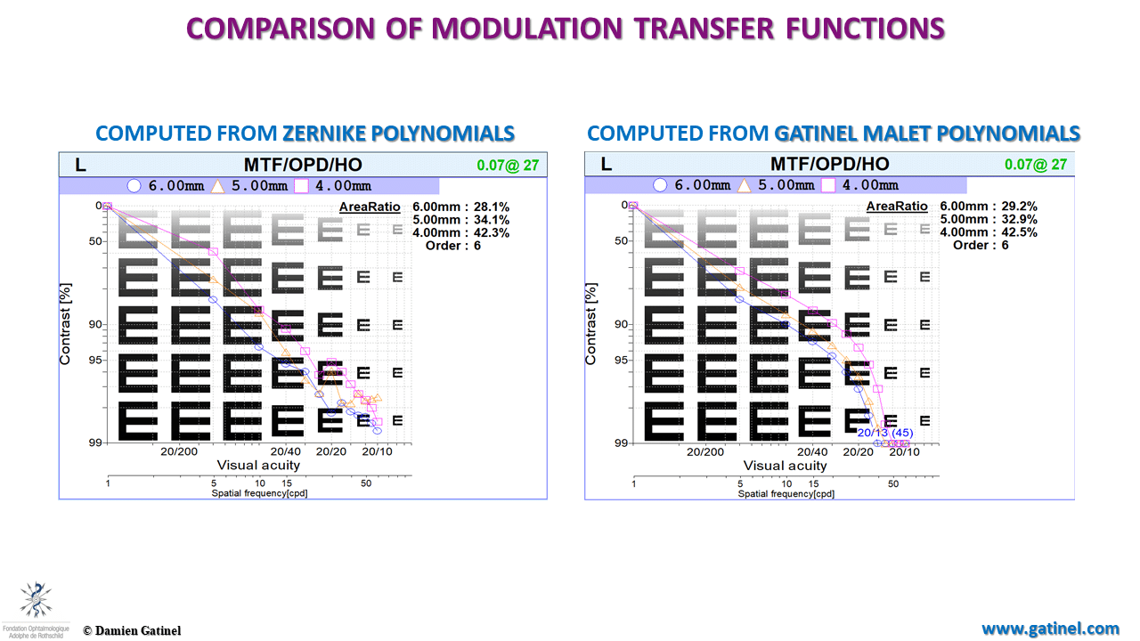
Comparison of the Modulation Transfer Functions.
Conclusion
The use of Zernike polynomials exposes the clinical scenario to the risk of interpretation bias, due to the mixture of lower order terms and higher order terms in some Zernike higher order modes.
In this striking example, the ocular wavefront decomposed with Zernike polynomials seemed to be deprived of myopic or hyperopic defocus; contrasting with the objective and subjective myopic refraction.
Zernike polynomials have undesirable characteristics such as masking the presence of defocus hidden in the higher order wavefront component, which also leads to overestimating the visual impact of the higher order wavefront component. The planning of aspheric photoablation profiles to increase the corneal multifocality should benefit from our new approach for wavefront analysis.
Laisser un commentaire