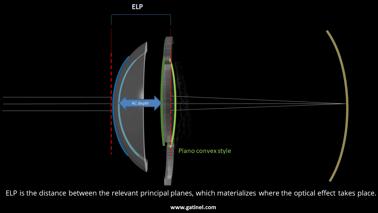
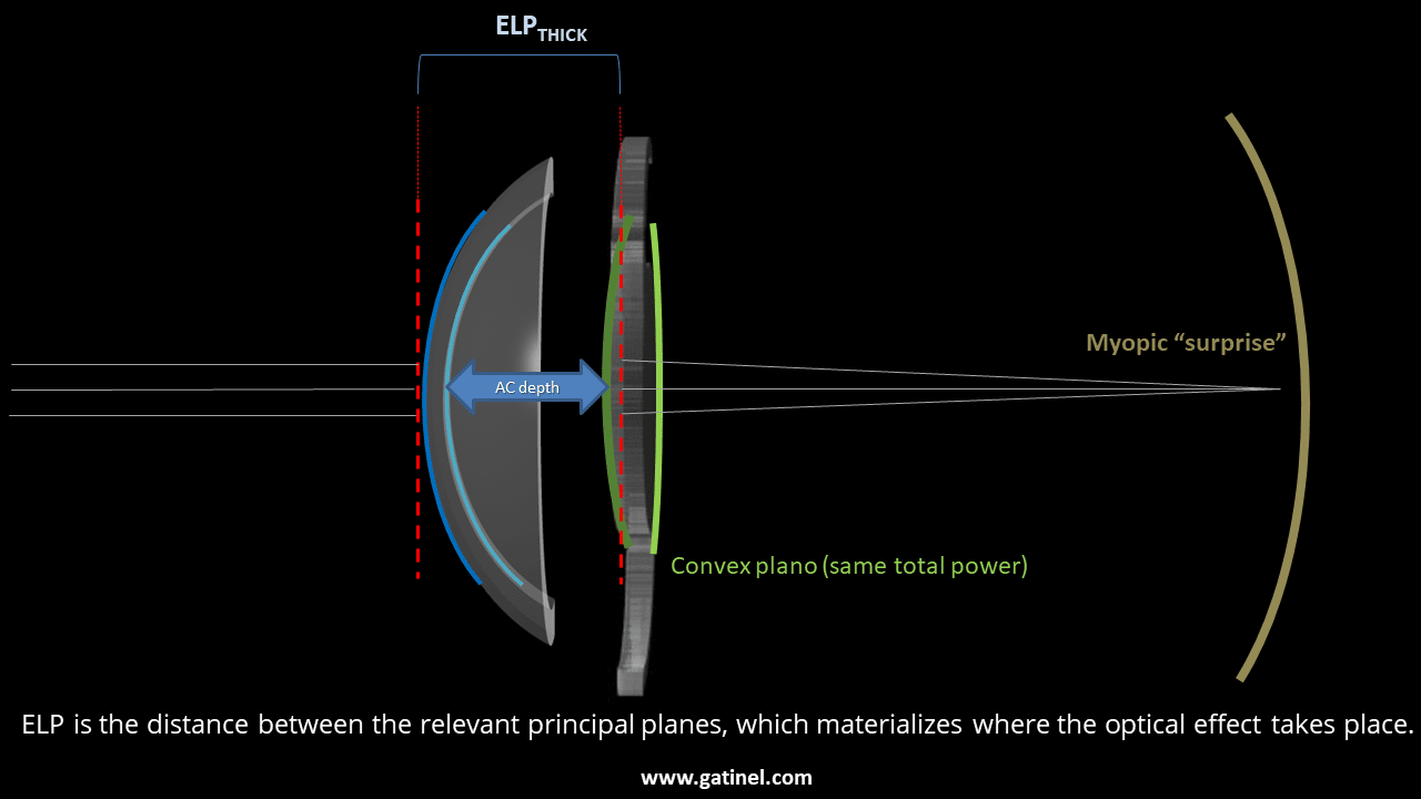
The Coddington shape factor relates to the distribution of the total IOL power, which can vary between the anterior face and the posterior surface. The more the anterior surface is curved (and therefore generates more optical power), the less the posterior surface must be (generating less optical power), and vice versa. The interest in modulating the power distribution via the degree of IOL’s bending arises either from non-paraxial optical considerations (giving less power to the anterior surface makes it possible to reduce the positive spherical aberration) or from industrial manufacturing processes (cast vs. molded IOLs). In a thick lens model, the variations in shape have a paraxial consequence because they directly influence the implant’s position of the principal planes. Roughly, these move « towards » the most optically powerful surface. This implies that two implants with the same index of refraction, the same labeled power, and the same thickness will not have the same optical position/behavior after implantation and therefore the same optical effect if their power distribution between the front surface and the rear surface is different (which is equivalent to a different Coddington shape factor value). These diagrams represent two implants of the same power and overall geometry (haptic structure), but with different optical designs. One of the implants is of the plano-convex style, where most of its optical power is provided by the back surface, causing a posterior displacement of the principal object plane of the implant. Conversely, the main object plane of the plano-convex style implant is more anterior. While the anatomical distance of these implants is the same (i.e., the distance from the corneal endothelium), the actual effective position of these implants differs. These differences explain the need to adjust the constants of IOLs, which, in practice, is equivalent in most IOL power calculation formulas to varying the predicted position of the implant by a constant increment. In the example shown, while the plano-convex design allows for emmetropia, it would result in slightly myopic refraction.
Coddington shape factor:
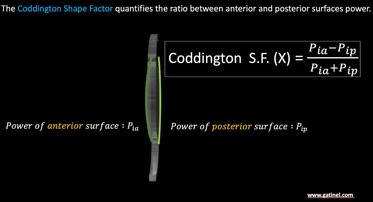
The Coddington shape factor is a dimensionless quantity that characterizes the degree of curvature asymmetry (or bending) of an intraocular lens (IOL). It is defined as the ratio of the difference to the sum of the powers of the anterior (Pia) and posterior (Pip) surfaces of the IOL.
The Coddington factor is sometimes expressed as the ratio of radii (Ria and Rip), and there is sometimes confusion between the two expressions in the literature. The above expression makes it possible to apprehend in a very intuitive way the effect of the design on the sign of the Coddington factor. An intraocular lens (IOL) with greater optical power on its anterior surface has a positive Coddington shape factor. Conversely, if the posterior surface contributes more to the overall power, the Coddington factor becomes negative. For example, a biconvex lens with a steeper front surface than back surface will have a positive shape factor. Indeed, it is necessary to consider the signs of the radii of curvature of each of the surfaces of the implant and their size in absolute value. In practice, most common IOLs are either biconvex lenses for positive implants or plane concave or biconcave lenses for negative IOLs (although there are also some concave-convex designs) for biconvex or biconcave implants (-1 <X <1), an expression can be used which calls for the absolute value of the radii of curvature and which easily allows visualizing the relationship between the front and rear radii. The following figure establishes these relationships for an IOL of refractive index ni immersed in saline solution (refractive index nss):
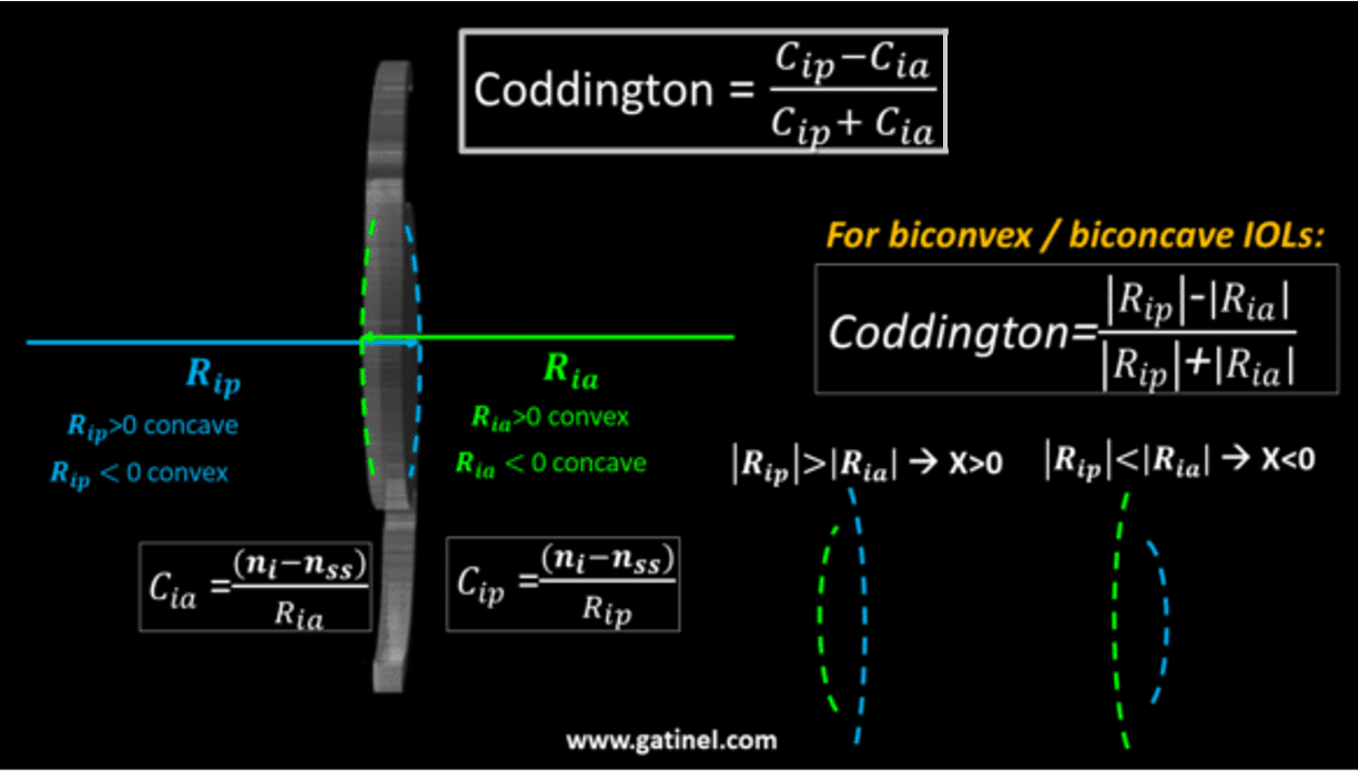
Ria is the radius of curvature of the anterior surface. Rip is the radius of curvature of the posterior surface.
Coddington shape factor, IOL power, and principal planes
Positive power IOL
*Most IOLs with positive power are manufactured as biconvex (Ria<0 and Rip>0). In this case, the sign of X depends on the numerator of its expression, as the denominator is always positive. If |Ria|>|Rip| (less power anteriorly, more power posteriorly), then X<0 – and vice versa. When the total power is balanced equally between the anterior and posterior surfaces, then Rip=Ria and X=0. The principal planes shift towards the most optically powerful surface: the anterior for positive values of X and the posterior for negative values of X.
Negative power IOL
*When an IOL has negative power, at least one of its surfaces is concave. For values of X between -1 and +1, the two surfaces are concave. The principal planes of the implant are moved to the more concave surface, which is anterior for X >0 and posterior for X<0. Below -1 and above +1, the implant adopts a concave-convex (X <-1) or convex-concave (X> +1) geometry. In this type of configuration, the principal planes of an implant are located « outside » the physical planes delimited by the IOL’s surfaces! This explains why the constant A suddenly « jumps » from one value to another (eg from 118 to 116) when considering a positive vs negative power for the IOL, so as to compensate for the sudden jump in the effective position of the implant (displacement of the main plane of the major object between the positive powers and the negative powers).
Designing an IOL with a given Coddington shape factor
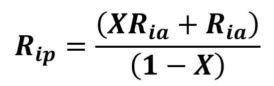
From the expression of the Coddington shape factor, we get the value of Rip as a function of X and Ria the following expressions correspond to biconvex or biconcave IOLs) One can substitute this to Rip in the formula giving the optical power of the thick IOL:
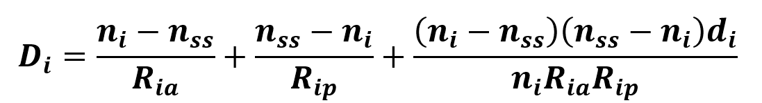
Hence, we obtain :
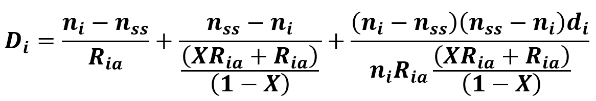
Solving this equation for Ria leads to this somewhat complex equation:
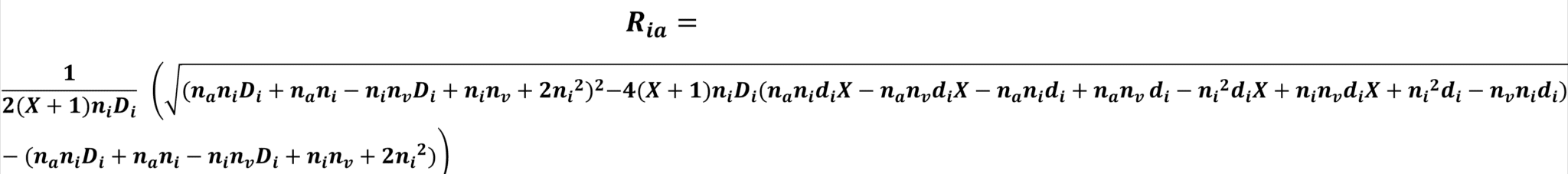
This enables us to calculate the value of the anterior radius of curvature of an IOL with a given total power (D_i) and thickness (d_i). For numerical applications, the central thickness of the implant can be chosen empirically using data from already manufactured lenses. The central thickness of positive power implants generally varies between 0.5 mm for low powers and 1.5 microns for high powers. Once obtained, the value of Rip can be obtained using the above-listed equation:
Interactive IOL bending design
Here you can design the shape of a positive power implant and another of negative power with the Coddington shape factor of your choice. The values of the anterior and posterior radii of curvature corresponding to the specified power, value of Coddington shape factor, and thickness will be calculated. Note the dramatic impact of the implant design on the position of the principal planes. This position is of major importance in the case of biometric formulas called “thick lenses.”