This page is dedicated to studying thick lens formulas that characterize the intraocular lens (IOL) paraxial properties, including power and effective position. The determination of the location of the principal planes allows a finer determination of the position of the IOL and justifies the switch to a thick lens model. The corresponding paraxial formulas allow the calculation of the power of the IOL’s anterior and posterior surfaces and the total IOL power taking its thickness into account. In addition, the determination of the position of its principal planes is necessary to establish with certainty the effective lens position (ELP). Finally, by virtue of Gullstrand’s formula, the ELP is an important variable for predicting the total power of the cornea + intraocular lens pair. At the end of this page, an interactive calculator allows you to calculate all these values and visualize the impact of the design of an IOL on the distribution of optical power between the front and rear surfaces, and on the position of the principal planes.
Preliminary remarks
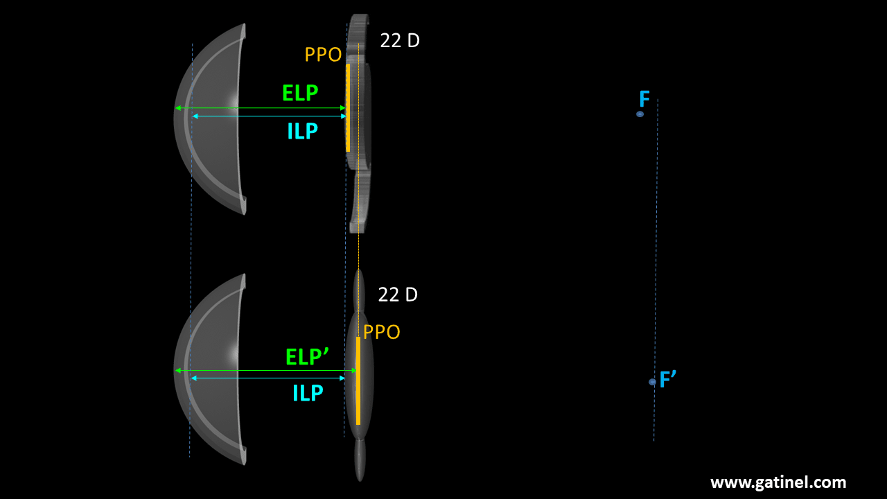
The optical design of monofocal IOLs varies from model to model. For the same paraxial optical power, one can, for example, choose to distribute the power equally on the front and the back surface (the curvatures are identical, and the implant is symmetrical). One can also choose to give more power to the back (posterior) surface of the implant (the radius of curvature of the posterior face will then be shorter than that of the anterior face). These choices generally result from non-paraxial considerations (control of spherical aberration) but have paraxial consequences as they influence the position of the principal planes. In a model of a pseudophakic eye with thick lenses, the position of the implant is referred to by that of its principal object plane. Two implants of the same power, whose anterior surface is located at the same distance from the same cornea (same internal lens position= ILP) but whose geometry is different, will not have the same refractive effect! This is because the geometry of the IOL influences the position of its principal planes (PPO : principal plane- object). The ELP (Effective Lens Position) is defined by the distance between the PPI (principal plane – image) of the cornea and the PPO, and the value of the ELP influences the value of the focal length of the cornea + IOL pair.
The Coddington shape factor is a variable that is calculated from the values of the anterior radius of curvature and the posterior radius of curvature of a thick lens. The value of the Coddington factor is proportional to the distribution of optical power between the anterior (front) surface and the posterior (back) surface of the IOL. For a biconvex implant, a positive value implies more power for the front surface and vice versa. The principal planes of the implants are positioned towards the most powerful surface. Hence, if we know the value of the paraxial power of the IOL and the Coddington factor, we can deduce the geometry of the IOL for a given thickness., and compute the position of its principal planes to determine the ELP. The paraxial optical power or vergence of an intraocular lens depends on the curvature of its front (anterior) and back (posterior) surfaces, as well as on its thickness. This power is also a function of the environment in which the IOL is located. After insertion into the eye during cataract surgery, the anterior surface of the implant is in contact with aqueous humor, and the posterior surface in contact with the vitreous cavity. The refractive indices of these compartments differ slightly from an isotonic solution (BSS) which is generally used as a reference for measurements of the paraxial power of an intraocular implantin vitro. The subsequent differences in terms of labeled vs. effective IOL power are generally small in magnitude.
Paraxial formulas
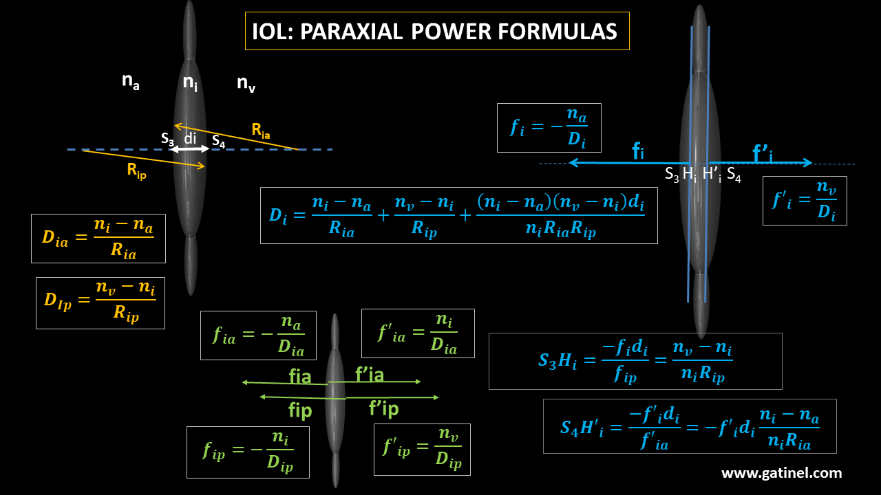
The following figure makes it possible to calculate for the anterior surface, the posterior surface, and the IOL assimilated to a thick IOL inserted in the eye: -the total paraxial power, -the object focal length, -the image focal length, -the position of the principal planes of the IOL
Numerical example
Let us consider the following IOL’s parameters: -the radius of curvature of the anterior face is Ria is 20.00 mm – the radius of curvature of the posterior face Rip is -16.00 mm -the lens thickness is di = 1.00 mm -the refractive index of the IOL is ni = 1.52 -the refractive index of aqueous humor is na = 1.337 -the refractive index of the vitreous is nv = 1.336
Power of the anterior surface of the IOL
The power of the anterior surface of the lens Dia is given by: Dia = (ns – na) / Ria = (1.52 – 1.337) /0.02000 = 9.15 D
Power of the posterior surface of the IOL
The power of the posterior surface of the lens Dip is given by Dip = (nv – ni) / Rip = (1.337 – 1.52) /0.01150 = 11.50 D
Focal distances from the anterior surface
We can now calculate the focal object and image distances : The object focal length is fia = -1.337 / 9.15 = – 146.12 mm The image focal length is f’ia = 1.52 / 9.15 = 166.12 mm
Focal distances from the posterior surface
The object focal length is fip = -1.52 / 11.50 = – 132.174 mm The image focal length is f’ip = 1.336 / 11.50 = 116.174 mm
Determination of the power of a centered system equivalent to the thick lens IOL
We use Gullstrand’s formula, which considers the distance between the vertexes of IOL’s refractive surfaces (i.e., the thickness of the lens). It allows to calculate of the power of the overall system (Di), made up of the anterior and posterior surface of the IOL: Di = Dia + Dip – di x (Dia x Dip) / ni = 20.58 D
Focal distances of the whole lens
These distances are established to the respective positions of the principal object and image planes of the lens (which will be determined below) The object focal length is given by: fi = -1.337/ Di = -1.52/ 20.58 = – 64.964 mm The image focal length is given by: f’i = 1.336 / Di = 1.336 / 20.58 = 64.915 mm
Position of the principal planes of the IOL
Principal object plane:
The distance from the vertex of the anterior face of the IOL is given by: S3Hi = -di x fi / fip = 0.492 mm The position of the principal object plane of the IOL characterizes its effective position in an eye model made of thick lenses.
Principal image plane
The distance from the top of the posterior face of the IOL is given by: S4H’i =- di x f’i / f’ia = = -0.391 mm
Interactive calculator for IOL design and principal plane positions
This calculator allows you, in addition to the calculation of the paraxial powers of the anterior and posterior surfaces of the IOL and its total power, to directly inspect the effect of the design of an implant on the position of the principal planes. Just select any value for the anterior vs posterior IOL surface apical radii, and the IOL power and Coddington shape factors are computed, among other variables.
The figure inserted in the spreadsheet makes it possible to visualize the impact of the design of the IOL on the position of the principal planes. The effective lens position (ELP) is defined as the distance between the principal image plane of the cornea and the principal object plane of the implant. For biconvex lenses (Ria>0, Rip<0), it is observed that the principal planes are moving to the steeper surface, which is the most powerful: in the presence of a negative (resp. positive) Coddington shape factor, the planes are closer to the posterior ( resp. anterior) lens vertex. Some IOL models are made so that IOL with positive power IOLs are biconvex, while negative power implants can adopt a convex (posterior face) – concave (anterior face) geometry. For convex-concave-like designs, the principal planes are located « outside » the physical space of the IOL! This explains the significant jump in the value of the A constant for certain IOLs according to the sign of their power. In general, this change towards the negative powers causes a displacement of the principal planes towards the cornea; one must then reduce the A constant to compensate for the reduction in the value of the effective position of the IOL! A the end of the page dedicated to the Coddington shape factor (IOL design), you can design IOLs of various power and bending to get more familiar with these concepts. A page is dedicated to the back calculation of the ELP in a thick lens paraxial pseudophakic eye model for which the refraction is known.
Laisser un commentaire