This page aims to demystify the concept of “principal planes,” which often appear to be quite “esoteric” to non-specialists. In a thick lens system, the principal planes are two hypothetical planes at which all the refraction can be considered to happen. They are used to establish a paraxial simplified model, making it possible to predict the path of light rays through an optical system made of thick elements. This system can be simple (a unique thick lens) or more complex: an assembly of thick +/- thin lenses. Biometric computational models that consider the cornea and the IOL as thick lenses use the notion of the principal plane. The principal planes have no physical existence: they are a theoretical construction intended to simplify the path of light rays within an optical system under paraxial conditions. There are two principal planes: the principal object plane, the other is called the principal image plane. If we know the position of the principal planes of the optical system, we can predict their behavior concerning rays close to the optical axis, the direction these rays will take after refraction by the system – under paraxial conditions.
Justification of principal planes
The underlying problem that justifies this model’s use is the « thickness » of the optical systems. There are two special situations: the diopter and the thin lens, that we had already encountered while studying the vergence formula, and systems made up of thin lenses. However, in some clinical situations, such as advanced IOL power calculation, the thickness of the cornea and especially that of the IOL cannot be neglected; otherwise, this will reduce the accuracy of the calculations.
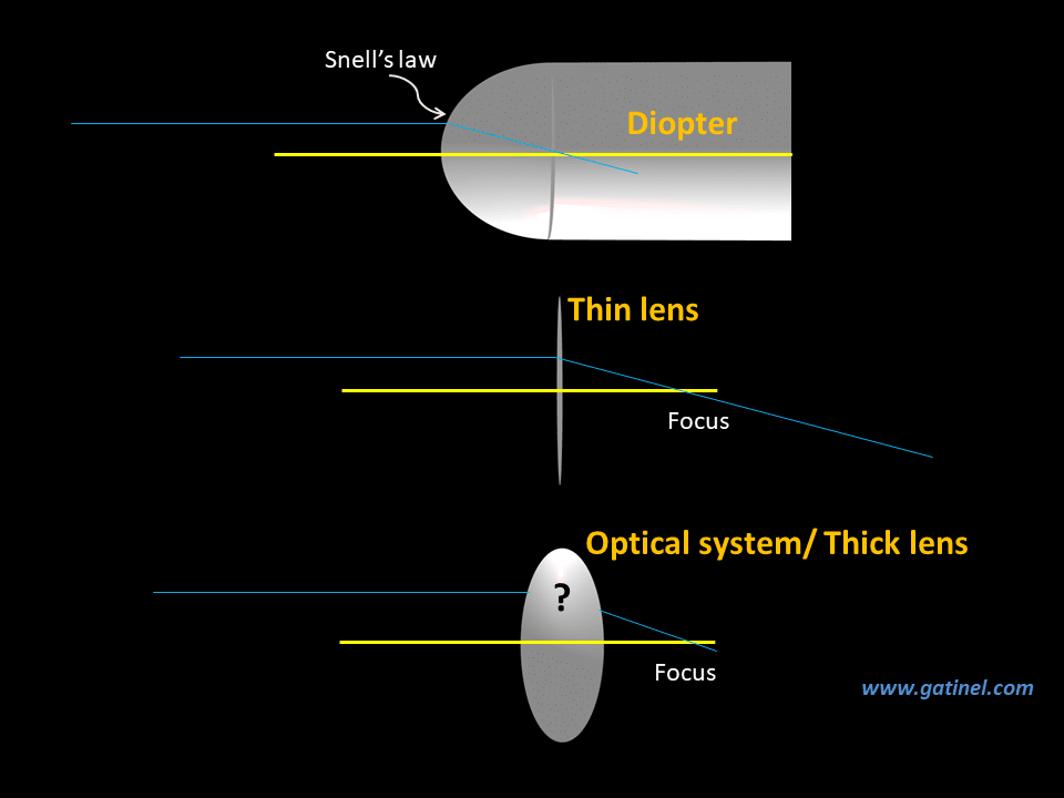
Referring to the above diagram: 1) The system has an infinite thickness: this is the case of the spherical diopter. According to Snell’s law, the incident ray is refracted in such a situation and continues to travel indefinitely within the diopter. 2) The system has zero thickness (or is very thin, with a thickness that can be neglected in practice). In this case, the behavior of the ray is predicted by the theory of thin lenses (this requires knowing the position of the focal points of the lens). If we know the location of the object and image focal points of the thin lens, we can determine the path of an incoming light ray. 3) However, when the thickness of the system is intermediate (and it can consist of one thick lens or more), the path taken by the light ray is more difficult to predict. One must take the thickness crossed by the light ray into account: the ray emerges from the system at a different height than the entry point of the incident point. This is because the incident ray parallel to the optical axis undergoes two successive refractions. We will focus on this next.
Refraction by a thick lens
In the case of a thin lens, one can act as if the incident parallel rays were « instantaneously » deflected towards the focal point. The height (distance to the optical axis) of the entrance ray is equal to the height of the exit ray. In the case of a more complex system such as a thick lens, there is a path « inside » the system that cannot be overlooked: it is responsible for a variation in the height at which the ray emerges. The only certainty is that the emerging ray from an incident ray close and parallel to the optical axis passes through the image focal point. The incident light rays (left) come from a distant source (at infinity) and hit the left surface of the thick lens, where they undergo the first refraction. The refracted rays then propagate in a straight line and then meet the straight surface of the lens, where they undergo the second refraction and are focused on the image focal point. We place ourselves here in ideal paraxial conditions, even if the diagrams, for didactic reasons, include representations apparently outside the paraxial situation.
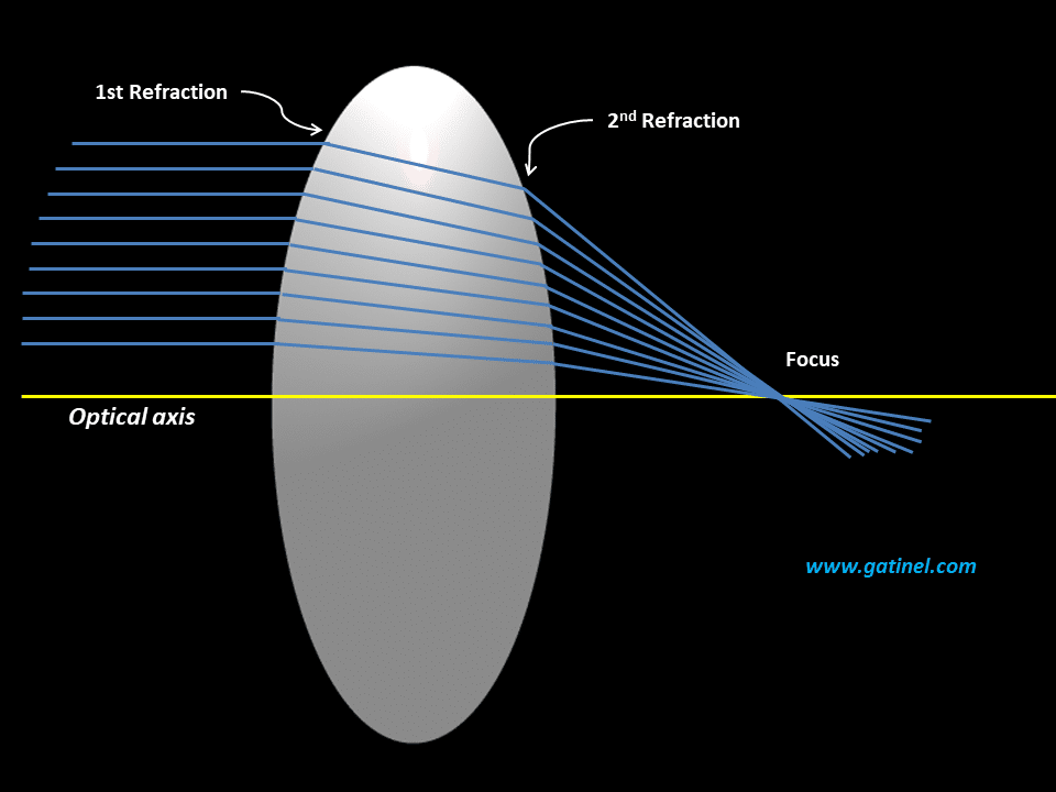
To perform the exact geometric trace and the calculation of the path of light through the lens (e.g., ray tracing using Snell’s law), each incident ray generates two consecutive refraction calculations (corresponding to the first and the second refraction). As we learned in the 1st part of this module devoted to the fundamentals of calculating the power of IOL, light takes the “shortest” optical path (the route that takes the least amount of time between two points) between the entrance and exit of a thick lens; it would certainly be possible to calculate this path if we know the geometry of the system and its refractive indices. We could use Snell’s law at each surface since Snell’s law follows precisely the principle of travel time minimization. It is simpler to define the existence of two principal planes, called the principal object plane and the principal image plane, which materialize the intersection between the incident rays (respectively emerging) parallel to the optical axis and the emerging rays (respectively incident) which pass through the image focus (respectively object) point. Rather than calculating the path of each incident ray (ex: ray-tracing), it is preferable to replace the complex system (thick lens) with a simple system made up of the principal planes.
Drawing of the principal image plane
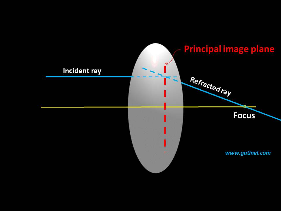
Principal image plane
Under paraxial conditions, all the incident rays parallel to the optical axis converge at a focal point after passing through a thick lens (each ray undergoes two consecutive refractions). To determine the location of the principal image plane, it is sufficient to draw an incident ray parallel to the optical axis and to know the path of the emerging ray (which passes to the image focal point after being refracted by the second surface of the lens). The path of these rays is extended, and a mark notes their intersection. If we repeat this for several incident rays parallel to the optical axis, we obtain the following plot:
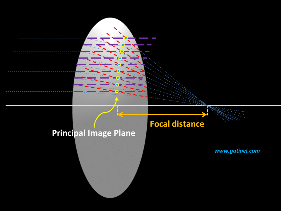
In this figure, the incident rays (in purple) and the emerging rays (in red) have been extended in dotted lines. Their intersection (cross-sectional dotted plots – yellow circles) defines the principal image plane. Interestingly, the envelope of these points is a straight perpendicular line (it would represent a plane in 3D) near the optical axis, that is to say, in paraxial conditions. This surface is slightly curved at a distance, but the concept of the principal plane only applies under paraxial conditions. It is possible to define a principal object plane by reasoning symmetrically.
Principal object plane
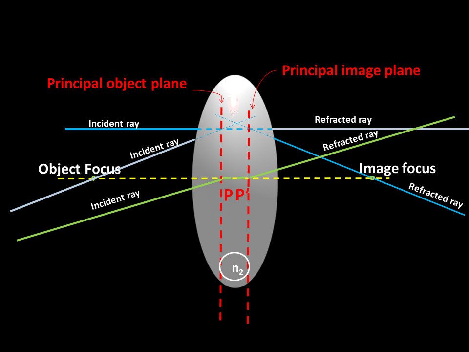
A similar plot can be made for the incident ray passing through the object focal point and refracted parallel to the optical axis to find the principal object plane. Several rays coming from the object focus are drawn towards the lens, and by definition, these rays are refracted, and exit in a direction parallel to the optical axis. The intersection of these rays defines the principal image plane.
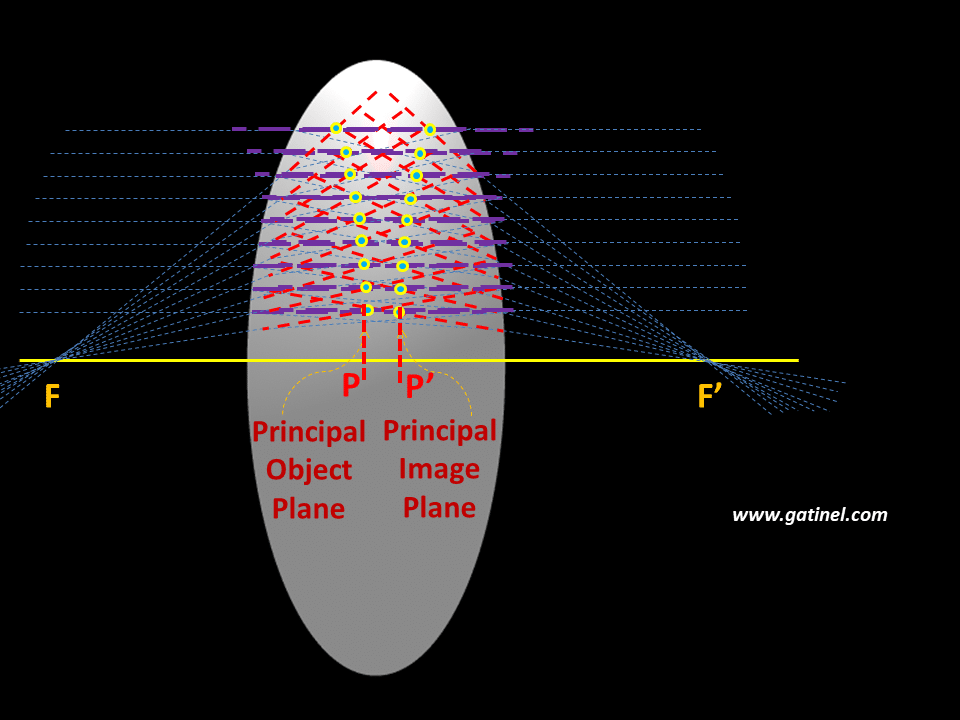
The intersection between the principal planes and the optical axis defines the principal points denoted P and P’. The location of these points is important because it serves as a landmark to define the image or object focal length of an optical system. The image focal length should be measured from P’ to the corresponding focal point and not from the vertex of the lens. It is represented by the segment P’F’. The object focal length is represented by the segment PF. When using a « thick lens eye model » for IOL power-related calculations, the position of the IOL used for paraxial computations refers to the position of its principal object plane. In such a thick lens model, the effective lens position refers to the distance between the principal image plane of the cornea and the principal object plane of the IOL. The distances used for paraxial calculations with thick lenses are defined to the principal planes. It is, therefore, necessary to determine the position of the principal planes of a system composed of thick lenses (e.g., cornea + IOL) to calculate its refractive properties accurately.
Paraxial properties of the principal planes
When a ray parallel to the optical axis meets a thin lens, it is instantly deflected towards the image focal point. In a thick lens, this deviation occurs when the ray reaches the principal image plane. Everything happens « as if » an incident light ray close and parallel to the optical axis was not deflected … until it meets the principal image plane: it is then refracted towards the image focus.
Likewise, by using the principle of reversibility of the path of light, we can establish that a ray passing through the object focus propagates without deviation until it meets the principal object plane and then be instantly deviated in a direction parallel to the optical axis (this principle was used to « trace » the location of the principal planes). When a ray meets the first principal plane, everything happens as if it transferred the ray to the second principal plane at the same distance (height) from the optical axis. The two principal planes have the property that a ray emerging from the lens appears to have crossed the rear principal plane at the same distance from the axis that the ray appeared to cross the front principal plane, as viewed from the front of the lens.
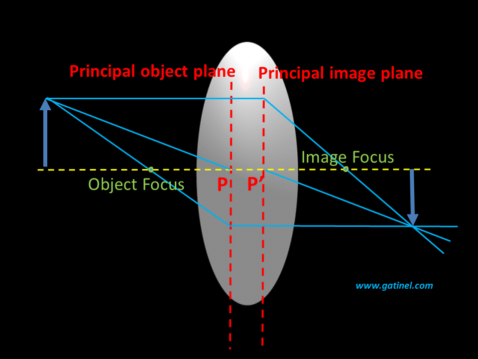
The lens can be treated as if all of the refraction happened at the principal planes. The magnification of an object located in the principal object plane (virtual object in the case where this principal object plane is in the lens or the optical system) is equal to 1: the corresponding image (virtual and located in the principal image plane!) is the same size and orientation as the object. The principal points P and P’ are the points where the principal planes cross the optical axis.
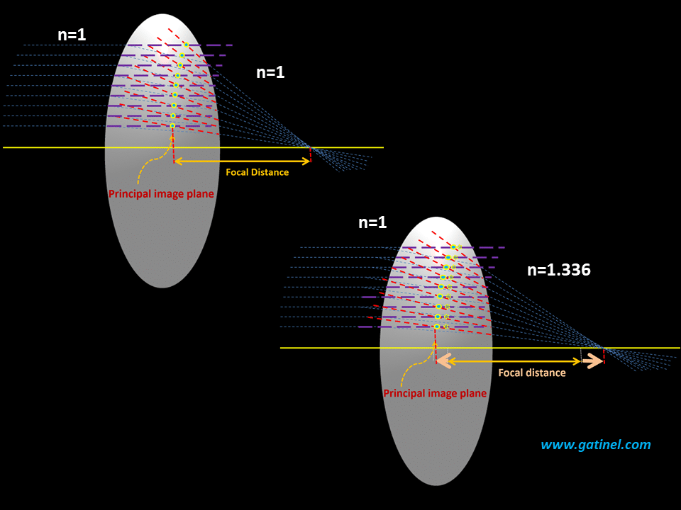
The principal planes’ construction allows reducing a « complex » optical system to a simplified system, which would be equivalent to a thin lens if the space between the principal planes would collapse. If the thick lens is in the air, the principal image plane is the same distance from the center of the lens as the principal object plane. When we study a system where the incident medium has a refractive index different from that of the medium where the image is formed (this is the case of the pseudophakic eye), this symmetry disappears. A modification of the value of the refractive index of the medium to the right of the lens influences the position of the principal image plane, and therefore the image focal length:
The position of the principal object plane is of particular importance concerning the actual position of the IOL in a thick lens pseudophakic eye model. In this model, the effective position of the implant corresponds to the distance between the principal image plane of the cornea and the principal object plane of the IOL. Therefore, we will study how to calculate the position of the principal planes from the main characteristics of the lens considered and the media in which it is inserted.
Position of principal planes
The position of the principal planes is equal to the ratio between the object or image focal length of the entire lens (or system), respectively, and: – the object focal length of the posterior face for the principal object plane. -the image focal length of the anterior face for the principal image plane. This is shown schematically in the following figures:
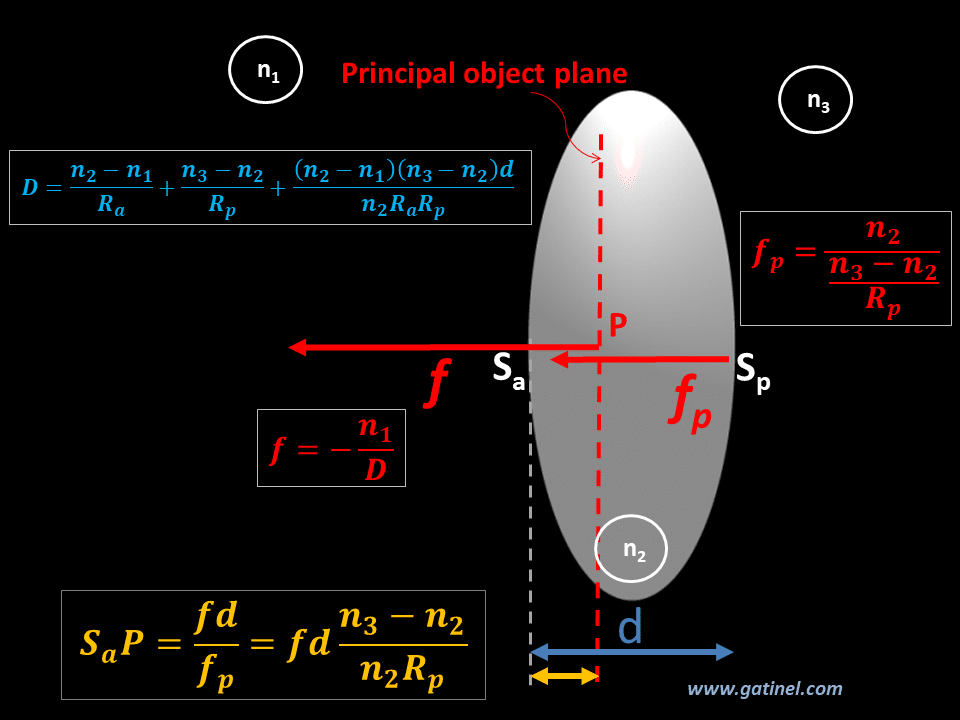
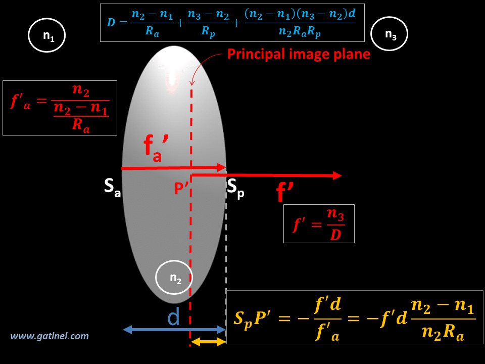
We can interpret them like this; the smaller f is, the greater the total power of the lens is compared to the power of the opposite face. Therefore, the principal plane is close to the vertex considered (anterior for the main object plane, posterior for the main image plane). This is important for understanding the effect of the Coddington shape factor on the principal planes of intraocular lenses. These planes move towards the more optically powerful surface and are otherwise centered when the implant has symmetrical surfaces. The next figure recapitulates the formulas, which gives the distance between the principal plane of the thick lens of radii Ra & Rp and its vertices Sa & Sp ( at its intersection with the optical axis of lens surfaces):
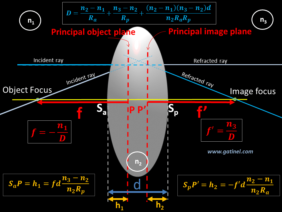
D is the total power of the lens. It is calculated according to Gullstrand’s formula, which takes into account the power of the front surface of the lens (of radius Ra), the power of the posterior surface of the lens (of radius Rp), and the thickness (d) of the lens as well as its index. Gullstrand’s formula makes it possible to calculate the total paraxial optical power of a thick lens, taking into account its thickness. It plays an important role in models that feature thick lenses; An elegant (but relatively complicated) demonstration of Gullstrand’s formula is available here: https://members.loria.fr/Roegel/loc/article-gullstrand.pdf f and f’ are the object and image focal length of the thick centered system, n1 the refractive index of the medium of the incident ray, d the thickness of the lens, n2 the refractive index of the lens, and n3 the refractive index of the medium of the refracted ray. f and f’ are referenced to the principal object and image planes. The position of the principal planes can be calculated using the formula mentioned above from the geometry of the implant: (power, curvature of the surfaces, refractive index, thickness of the implant), and by replacing n1 with the air refractive index (1) and n3 by the value of the aqueous humor’s refractive index, ex: 1.337). The curvatures (power) of the front and rear faces of the thick lens, the variations in the refractive index of the media logically influence the position of each principal plane. As stated above, the position of the principal planes logically moves towards the most optically powerful surface. When the two surfaces of the thick lens are of equivalent power, the principal planes occupy a middle position. If the lens has an asymmetric geometry (like most intraocular implants used in cataract surgery), we cannot, therefore, identify the position of the principal planes with that of the center of the lens, or suppose that these principal planes will be located at equal distance from the center of the implant.
Principal planes and intraocular lenses (IOLs)
We could identify the IOL position as the distance between the anterior vertex of the cornea and the anterior surface of the implant. Still, given the different geometries, refractive indices, etc., of implants as « thick lenses, » this choice would expose to uncertainties. Intraocular lens implants are thick lenses: to improve refraction control after implantation and establish reliable comparisons in terms of position, one must measure the position of a given IOL from its principal object plane. The position of the principal object plane to the vertex of the IOL does not depend on its effective position in the eye. Still, the refractive effect of the implant depends on its effective position in the eye (i.e., the anatomical position of the IOL in the eye after cataract surgery AND the effective position of its principal object plane). The position of the principal object plane of the IOL defines the effective position of the IOL. The focal length of the implant is defined from the principal image point (this length is equal to the distance between the principal image point and the image focus).The differences in the position of the principal planes concerning the geometry of the implant partly explain the need to adjust constant values such as “constant A” (SRK T formula) or the triplet « a0, a1, and a2 » (Haigis formula). Now that we have grasped the importance of the concept of the principal plane in the context of a thick lens pseudophakic eye model, we can calculate the position of the principal planes of the cornea, an IOL, and a system that combines the two. Some specific pages are devoted to calculating the principal planes of the cornea and the calculation of the principal planes of an IOL.
Laisser un commentaire